
working principle of lvdt
The working principle of linear variable differential transformer LVDT is a passive inductive transducer and is commonly employed to measure force or weight, pressure, and acceleration LVDT applications, etc. Which depends on the force in terms of the amount and the direction of displacement of an object.
working principle of the linear variable differential transformer.
Construction
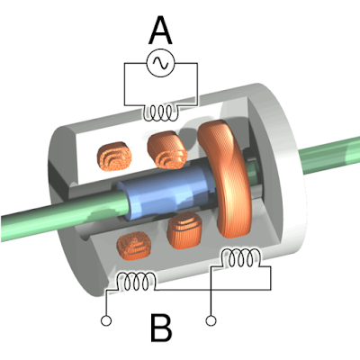
LVDT output voltage formula It consists of one primary p and two secondary windings Working of LVDT S1 and S2 which are placed on either side of the primary mounted on the same magnetic core. The magnetic core is free to move axially inside the coil assembly and the motion being measured is mechanically coupled to it advantages of LVDT.
The two secondaries S1 and S2 have an equal number of turns but are connected in series opposition so that emf E1 and E2 induced in them are 180 degrees out of phase with each other and, hence cancel each other out. The primary is energized from a suitable A.C. source LVDT diagram.

Working
- when the core is in the center the induced voltage E1 and E2 are equal and opposite. Hence they cancel out and the output voltage Vo is zero.
- When the externally applied force moves the core towards coil S2, E2 is increased but E1 is decreased in magnitude though they are still antiphase with each other
- The net voltage available is E2-E1 and is in phase with E2
- Thus from the above discussion, we find that the magnitude of Vo is a function of the distance moved by the core and its polarity or phase indicates in which direction it has moved
- If the core is attached to a moving object, the magnitude of Vo gives the position of that object.
Characteristics of a typical LVDT
- Size of lvdt diagram – Diameter-10mm and length-15mm.
- Size of the core-Diameter 2.5mm and length 10mm.
- Primary winding resistance-120 ohm.
- Primary winding inductance- 11.5 mH at the null position.
- Maximum input voltage sensitivity- 6 volts.
- Linearity range- greater than 5% of full-scale output voltage +-2.5mm.
Advantage
- It gives a high output and therefore many times there is no need for intermediate amplification devices.
- The transducer possesses a high sensitivity as high as 40 V/mm.
- It shows a low hysteresis and hence repeatability is excellent under all conditions.
- Most of the LVDT consumes a power of less than 1w.
- Less friction and less noise due to the absence of sliding contacts.
- These transducers can usually tolerate a high degree of shock and vibration without any adverse effects.
- It can operate over a temperature range from -265 degrees to 600 degrees.
- It is available in radiation-resistance design for operation in nuclear reactors.
Disadvantages
- These transducers are sensitive to stray magnetic fields but shielding is possible. This is done by providing a magnetic shield with longitudinal slots.
- Relatively large displacements are required for appreciable differential output.
- The receiving instrument must be selected to operate on A.C. signals or a demodulator network must be used if a D.C. output is required.
- Several times, the transducer performance is affected by vibrations.
- The dynamic response is limited mechanically by the mass of the core and electrically by the frequency of applied voltage. The frequency of the carrier should be ten times the highest frequency component to be measured.
Applications
- Measurement of material thickness in hot or slab steel mills.
- In accelerometer
- Jet engine controls in close proximity or exhaust.
- LVDT is not suited for fact-dynamic measurements on account of the mass of the core.
Capacitive Transducer
Operates on the principle of variation in capacitance produced by the physical quantity being measured.
Advantages
The major advantages of capacitive transducers are.
- Require an extremely small force for operation hence very useful for use in a small system.
- Extremely sensitive.
- Require small power for operation.
- High output impedance…therefore, loading effects are minimum.
- The frequency response is good.
- A resolution of the order 2.5 multiplying 10 to the power -3mm can be obtained.
- Can be used for applications where stray magnetic fields render the inductive transducers.
Disadvantages– The principal disadvantages of capacitive transducers are.
- The metallic parts must be insulated from each other. The frames must be earthed to reduce the effects of stray capacitances.
- They show non-linear behavior several times on account of the edge, hard rings must be used to eliminate this effect.
- The cable connecting the transducer to the measuring points is also a source of error. The cable may be a source of loading resulting in loss of sensitivity. Also, loading makes the low-frequency response poor.
Use-The capacitive transducers are used for the following purpose.
- To measure both linear and angular displacement.
- To measure force and pressure.
- Used as a pressure transducer in all those cases where the dielectric constant of a medium changes with pressure.
- To measure humidity in gases.
- Used in conjunction with mechanic modifiers for measurement of volume, density, weight, liquid level, etc.
Piezoelectric Transducers | piezoelectric transducer working principle
piezoelectric transducer diagram materials- A piezoelectric material is one in which an electric potential appears across a certain surface of a crystal if the dimensions of the crystals are changed by the application of a mechanical force piezoelectric sensor.
This potential is produced by the displacement of external charges. The effect is reversible conversely, if a varying potential is applied to the proper axis of the crystal, it will change the dimension of the crystal thereby deforming it.
This effect is known as the piezoelectric effect. Elements exhibiting piezoelectric quantities are sometimes known as electro-resistive elements. Common piezoelectric materials are ammonium dihydrogen phosphate, Rochelle salts, lithium sulfate, dipotassium tartrate, potassium dihydrogen phosphate, quartz, and ceramics A and B.
There are two main groups of piezoelectric crystal
1. Natural crystals- such as quartz and tourmaline.
2. Synthetic crystals- such as Rochelle salt, lithium sulfate, dipotassium tartrate, etc.
Working
A crystal mode of operation of piezoelectric devices employed for measuring the varying force applied to a simple plate is shown in the figure above. The magnitude and polarity of the induced charge on the crystal surface are proportional to the magnitude and direction of the applied force. The charge at the electrode gives rise to voltage E.
Advantages
- High-frequency response.
- Small size.
- High output.
- Rugged construction,
- Negligible phase shift.
Disadvantages
- Output is affected by changes in temperature.
- Can not measure static conditions.
Applications
- Accelerometer.
- Pressure cells.
- Force cells.
- Ceramic microphones.
- photograph pick-up.
- Cartridges.
- Industrial cleansing apparatus.
- Under-water detection system.
Related Topic – click here
- What Is A Diode? Working Principle & Types | Different Types Of Resistors
- What Is Synchronous Speed? | Types & Advantages Of DC Motors
- Working Principle Of Linear Variable Differential Transformer | Construction & Piezoelectric Transducers
- Three-Phase Induction Motor | 3-Phase Induction Motor Principle
- Introduction To Electrical Transformer | Definition, Construction & Parts Of A Transformer | Types Of Transformers
- DC Generator | Principle Of Operation, Construction, Types Of Generators & Application
- What Is DC Motor? | Principle Of DC Motor & Types Of DC Motors
- Diode-Circuits |Diode Convention, Transformer Rectifier & Objective Questions With Answer


