
What Is Cascade Transformer? Generation Of AC high-voltage
cascade transformer
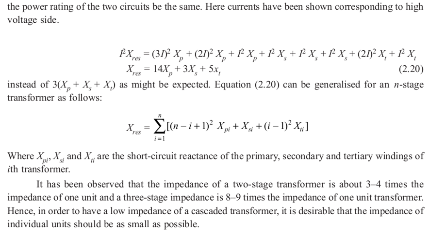
A high-voltage source consisting of a limited number of step-up transformers with their secondaries in series, the primary of each after the first being supplied from a pair of taps on the secondary of the preceding.
Most of the present-day transmission and distribution networks are operating on AC voltages and hence most of the testing equipment relates to high A.C voltages. Even though most of the equipment on the system are 3-phase systems, a single-phase transformer operating at power frequency is the most common form of HVAC testing equipment.
Test transformers normally used for the purpose have low power ratings but high voltage ratings.
These transformers are mainly used for short-time tests on high-voltage equipment.
The currents required for these tests on various equipment are given below:
Insulators, C.B., bushings, Instrument transformers = 0.1– 0.5 A
Power transformers, h.v. capacitors. = 0.5–1 A
Cables = 1 A and above the design of a test transformer is similar to a potential transformer used for the measurement of voltage and power in transmission lines. The flux density chosen is low so that it does not draw a large magnetizing current which would otherwise saturate the core and produce higher harmonics.
Cascaded Transformers:-
For voltages higher than 400 KV, it is desired to cascade two or more transformers depending upon the voltage requirements. With this, the weight of the whole unit is subdivided into single units and, therefore, transport and erection become easier. Also, with this, the transformer cost for a given voltage may be reduced, since cascaded units need not individually possess the expensive and heavy insulation required in single-stage transformers for high voltages exceeding 345 kV. It is found that the cost of insulation for such voltages for a single unit becomes proportional to the square of operating voltage.
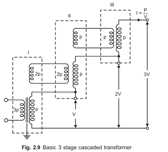
Fig. 2.9 shows a basic scheme for cascading three transformers.
The primary of the first stage transformer is connected to a low voltage supply. A voltage is available across the secondary of this transformer.
The tertiary winding (excitation winding) of the first stage has the same number of turns as the primary winding and feeds the primary of the second stage transformer.
The potential of the tertiary is fixed to the potential V of the secondary winding as shown in Fig. 2.9. The secondary winding of the second stage transformer is connected in series with the secondary winding of the first stage transformer so that a voltage of 2 V is available between the ground and the terminal of secondary of the second stage transformer.
Similarly, the stage-III transformer is connected in series with the second-stage transformer. With this the output voltage between the ground and the third stage transformer, secondary is 3 V. it is to be noted that the individual stages except the uppermost must have three-winding transformers.
The uppermost, however, will be a two-winding transformer.
Fig. 2.9 shows the metal tank construction of transformers and the secondary winding is not divided.
Here the low-voltage terminal of the secondary winding is connected to the tank.
The tank of the stage-I transformer is earthed. The tanks of stage-II and stage-III transformers have potentials of V and 2 V, respectively above the earth and, therefore, these must be insulated from the earth with suitable solid insulation.
Through h.t. bushings, the leads from the tertiary winding and the h.v. winding is brought out to be connected to the next stage transformer.
However, if the high voltage windings are of mid-point potential type, the tanks are held at 0.5 V, 1.5 V, and 2.5 V, respectively. This connection results in a cheaper construction and the high voltage insulation now needs to be designed for V/2 from its tank potential.
The main disadvantage of cascading the transformers is that the lower stages of the primaries of the transformers are loaded more as compared with the upper stages.
The loading of various windings is indicated by P in Fig. 2.9. For the three-stage transformer, the total output VA will be 3 VI = 3 P and, therefore, each of the secondary winding of the transformer would carry a current of I = P/V.
The primary winding of the stage-III trans-former is loaded with P and so also the tertiary winding of the second stage transformer.
Therefore, the primary of the second stage transformer would be loaded with 2 P. Extending the same logic, it is found that the first stage primary would be loaded with P. Therefore, while designing the primaries and tertiaries of these transformers, this factor must be taken into consideration.
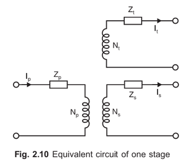
The total short circuit impedance of a cascaded transformer from data for individual stages can be obtained. The equivalent circuit of an individual stage is shown in Fig. 2.10.
Here Zp , Zs , and Zt , are the impedances associated with each winding. The impedances are shown in series with an ideal 3-winding transformer with a corresponding number of turns Np, N s, and N t
The impedances are obtained either from calculated or experimentally derived results of the three short-circuit tests between any two windings taken at a time.
Also read,


