
Sources
Sources are of two types:
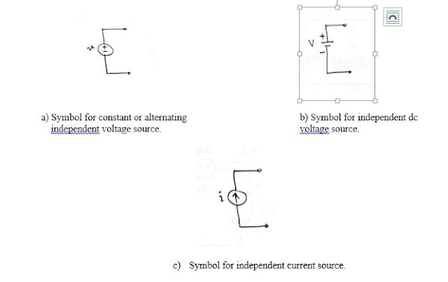
- Voltage source
- Current source
Similarly, sources can also be categorized as:
- Independent source
- Dependent source
Definition: An ideal independent source is an active element that provides a specified voltage or current which is completely independent of other current elements.
An ideal dependent (or controlled) source is an active element in which the source quantity is controlled by another voltage or current.
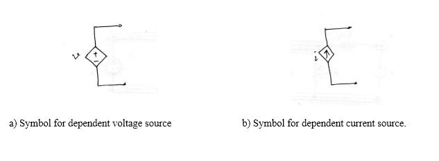
There are four types of dependent sources:
- Voltage-controlled voltage source;
- Current controlled voltage source;
- Voltage-controlled current source;
- Current controlled current source.
Dependent sources are used in modeling elements such as transistors, op-amps, etc.
Example of dependent source in a circuit:
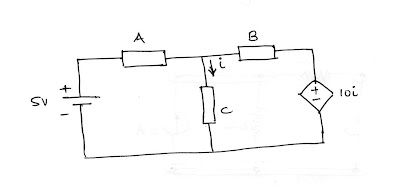
- The value of the dependent source is 10i Volts (it’s a voltage source NOT a current source).
- The voltage source comes with polarity (+ -), while the current source comes with an arrow.
- Any voltage (dependent or independent) can supply any current to ensure its terminal voltages remain as stated (rated). Therefore, for the voltage source, we know the voltage but not the current unless analyzed.
- Similarly, any current (dependent or independent) source can supply the necessary voltage to ensure the stated current flow. Therefore, for the current source, we know the current but the voltage unless analyzed.
- An ideal source can therefore produce an infinite amount of energy.
- Sources can supply as well as absorb power.
Ex: Calculate the power supplied or absorbed by each element of the circuit below:
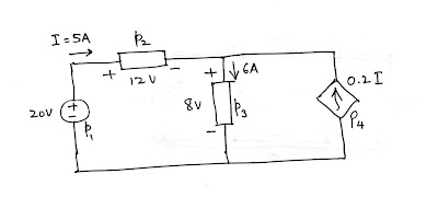
| p = +vi (power absorbed)p=-vi (power supplied)p1 = -20 x 5 = -100Wp2 = 12 x 5 = 60Wp3 = 8 x 6 = 48Wp4 = -8 x 0.2(5) = -8W | p1 and p4 are supplying power;p1 + p2 + p3 + p4 = -100 + 60 + 48 -8 = 0WTotal power supplied is equal to total power absorbed. |
Ex: Calculate the power supplied or absorbed by each element of the circuit below:
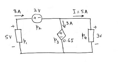
p1= -5 x 8= -40W
p2= 2 x 8= 16W
p4=3 x 5 = 15W
p3 = 0.6(5) x 3 = 9W
p1 + p2 + p3 + p4 = -40+16+15+9 = 0
Also read,

