
Vibration Galvanometer
Vibration galvanometers are the AC galvanometers used to measure alternating current and electromotive force (EMF) of various circuits. These galvanometers are also used as tuned detectors in the power frequency and low audio-frequency ranges. Vibration galvanometers are designed to be used as detectors for the measurement of frequency from 5 Hz to 1000 Hz. These galvanometers are highly sensitive for the frequency range under 200 Hz. These galvanometers are most commonly used as null detectors in AC bridges.
Types of Vibration Galvanometer
Vibration galvanometer consists of one type mentioned below:
Moving Coil type Vibration Galvanometer
Construction of Moving coil-type Galvanometer

A moving-type Vibration galvanometer consists of a moving coil between the poles of permanent magnets. The frequency oscillation of the coil is very high. This high value is achieved by using the control constant of a large range and a moving system of small inertia. It consists of two suspension wires consisting of a strip of a phosphor-bronze. These two suspensions carry the coil and a mirror.
Working Principle of Moving Coil Type Galvanometer
The beam of light is produced on the mirror M and this beam is deflected on the scale. When alternating current is passed through the coil, an alternating torque is produced which acts on a reflected light and the reflected spot of light is drawn out in the form of a band of light. The natural frequency of oscillation of a coil overlaps with the supply frequency due to resonance and the length of the band of light is maximum. The resonance curve of the vibration galvanometer is sharply peaked due to low damping. Its deflection is very small when the frequency of applied current differs by a small amount from its resonance frequency.
Theory of Vibration Galvanometer

If The current passing through the galvanometer is, then the motion of the coil is:

Where G is the deflection constant and D is the damping constant.
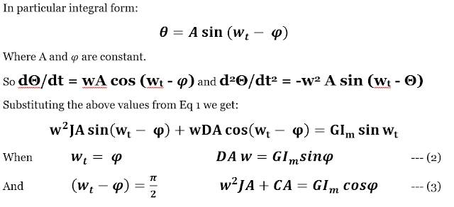
Where J is the Inertia constant.
The phase angle φ has no significance and is eliminated by squaring and adding in Eq. 2 and 3.

This equation represents the amplitude A of the resulting oscillation for a sinusoidal alternating current of peak value (Im) flowing through the moving coil of the galvanometer.
Application (Uses) of Galvanometer
- Ammeter: Galvanometers can be used as the basis for ammeters, which measure the magnitude of electric current in a circuit. By adding shunt resistors or other components, galvanometers can be modified to measure a wide range of current values.
- Voltmeter: When used in combination with a high-resistance shunt, a galvanometer can be converted into a voltmeter. Voltmeters are used to measure voltage or potential difference across a component or circuit.
- Detector in Scientific Instruments: Galvanometers are used as detectors in various scientific instruments, such as spectrometers, oscilloscopes, and seismographs, where they help in measuring and recording small electrical signals.
- Compasses: In the past, galvanometers were used in compasses to detect and display the direction of electric currents, such as those produced by the Earth’s magnetic field. These are known as tangent galvanometers.
- Testing and Troubleshooting: Galvanometers are often used in testing and troubleshooting electronic circuits to detect the presence and direction of electric currents, helping engineers and technicians identify faults.
- Environmental Monitoring: Galvanometers can be utilized in environmental monitoring systems to measure small electrical signals produced by sensors, such as those detecting changes in temperature, humidity, or light.
- Geophysics: In geophysical exploration, galvanometers are used to measure electrical resistivity and conductivity in the Earth’s crust, aiding in the detection of underground structures or resources.
- Feedback Control Systems: Galvanometers are employed in feedback control systems, such as laser beam steering systems, to precisely control the position or orientation of a device.
- Laser Scanning and Printing: Galvanometer-based scanners are used in laser scanning systems and laser printers to rapidly and accurately direct laser beams to create images or patterns.
- Galvanometer-Based Displays: Some laser projectors and laser light shows use galvanometers to control the movement of laser beams, creating intricate visual displays and animations.
For daily Job updates – cgjobs.live
