TYPES OF RESISTORS
The resistor is the most widely used electrical and electronic device. Every radio, television set, and control circuit has a resistor or resistor. This component is used to provide resistance. It is designed to be used at a fixed value or as a variable-value device.
FIXED RESISTORS
The fixed resistor is the simpler of the two types. It is made so that you cannot change the resistance. Some carbon-fixed resistors are shown in Figure 1. These are carbon composition and have a cover of black, brown, or green plastic. A color code is used to give the value of the resistor.
Fixed wire-wound resistors are available for use when the wattage rating is higher than 2 watts. Carbon-composition resistors come in 1/8, 1/4, 1/2, 1, and 2-watt sizes. The physical size tells the rating. You get used to the wattage rating when working with resistors. The larger the resistor, the higher the wattage rating is.
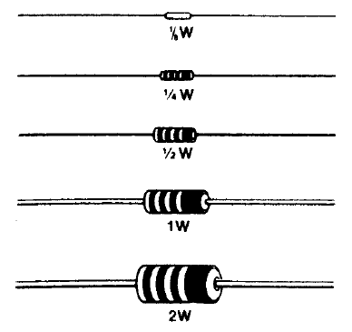
The larger the resistor, the easier it is for it to dissipate heat. Since resistors put up resistance to current flow, they also drop voltage. The energy has to be dissipated as heat. Thus, the surface of the resistor must be large enough to allow the heat to be dissipated.
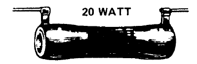
Figure 2 shows some fixed wire-wound resistors. These are made of high-resistance wire wound on an insulating core with a ceramic coating. They usually are large enough so that the resistance of the unit can be stamped on it.
The symbol for a fixed resistor is shown in Figure 3. Note how the symbols vary for different users. A is the standard EIA (Electronics Industries Association) symbol. B is usually used by foreign manufacturers and occasionally by American makers of industrial equipment. C is seldom encountered, but it is sometimes used in schematics for industrial equipment and can be seen in some refrigeration and air-conditioning electrical schematics.

VARIABLE RESISTORS
Some resistors are variable. This means that the amount of resistance can be changed. Variable resistors may be either carbon composition or wire wound. These resistors are used for special circuits. On these circuits, the amount of voltage or current that is delivered must be varied. A common example is the volume control on your radio or television set (Figure 4).
Variable resistors are easily identified because they have three connections for leads. The center lead is usually the variable contact. A variable resistor that is connected to a circuit at all three points is called a potentiometer (see Figure 5).
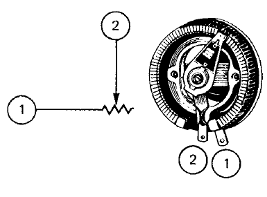
A potentiometer is often referred to as a pot. Usually, a potentiometer is used to vary the voltage. The device is connected across a voltage source by placing it directly across the battery or power source. The variable arm is then used to change the voltage that is available from the potentiometer. The rheostat is a variable resistor. It is used by connecting it in series, not across the voltage source, as was the case with the potentiometer.
Rheostats are designed to handle higher currents than potentiometers. Very few rheostats are used today because their jobs are being done by semiconductors. Usually, a rheostat is connected to a circuit at only two points. A symbol for the rheostat is shown in Figure 5.
Variable resistors have a wide range of adjustments. For example, volume controls typically use carbon resistors. Resistance ratings can be adjusted from 0 to 10 million ohms. Another way to state these values is from 0 to 10 mega-ohms (mega means million).
Many potentiometers have what is called a nonlinear resistance element. This simply means that resistance does not change at a fixed, or uniform, rate as adjustments are made. Usually, they are small, or fine, with changes at the low end. At the high end, settings lead to large resistance changes. This non-uniform resistance leads to what is called a tapered control. Such devices are usually used to adjust sound volumes and are called audio taper resistors.
There are also linear taper potentiometers. They have a uniform change of resistance as the settings are adjusted. They look exactly the same as the audio taper. When replacing a potentiometer, you must be very careful not to use a linear taper in a volume control circuit or, worse yet, an audio taper in a control circuit. This is one of the things that you, as a technician, must be aware of in making repairs. Do not try to substitute a volume control of the same resistance for a control circuit potentiometer. You will find it very difficult to make the required adjustments in the control circuit.
Wattage ratings are usually marked on the rheostat or potentiometer. It is difficult to tell the wattage rating by just observing the device. It takes practice to be able to tell the difference between various wattage ratings.
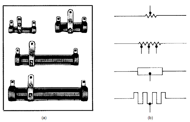
TAPPED RESISTORS
Tapped resistors are used in some circuits. They have taps for easy connections. They are usually wire wounds, although some are carbon. Figure 6(a) shows samples of the tapped resistor. Figure 6(b) shows the schematic representation of tapped resistors.
The ceramic coating is left off the wire where the tap is to be made. This allows a sliding connection so that the tapped resistor can be made into a variable resistor or adjusted as needed.
VARIABLE RESISTORS
A variable resistor may be made of carbon or it may be wire-wound. The idea behind the variable is to make it adjustable to meet the needs of the circuit. You are most familiar with the variable resistor as a volume control on a radio or television set. This is a variable carbon-composition type of resistor and controls a circuit to allow for increases or decreases in volume, as you desire.
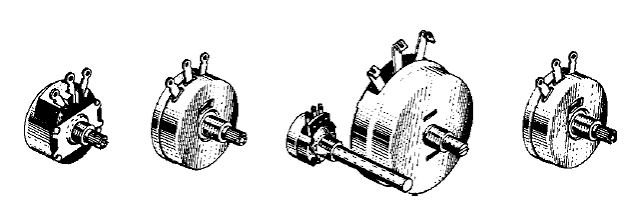
A variable resistor has a movable contact that is used to adjust or select the resistance value between two terminals. In most uses, the variable resistor is a control device. It is made in many sizes and shapes. Figure 7(a) shows some of these types. The shafts of most variable resistors have knobs placed on them to make them easier to use. However, some are made to be adjusted by the insertion of a screwdriver blade in a slot on the resistor. Many adjustable resistors are used in controls for air-conditioning and refrigeration systems. Figure 7(b) shows the schematic representation for variable resistors.

FUSIBLE RESISTORS
In some cases, the resistor has a purpose other than providing resistance. One type is used to protect the equipment or circuit against excess current surges.
This type of resistor, called a fusible resistor, is built to fail before damage is done to more expensive parts. Such units are often made to plug into a socket {see Fig. 8(a)}. Figure 8(b) shows the schematic symbol for a fusible resistor.
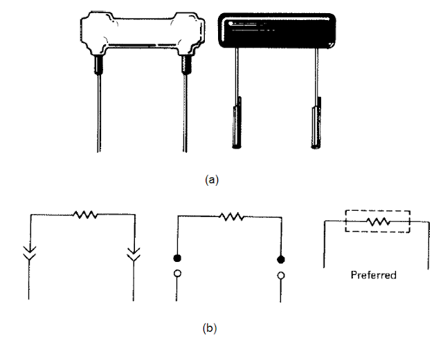 |
| Figure 8 (a) Fusible resistors. (b) Fusible-resistor symbol. |
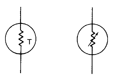
TEMPERATURE COMPENSATING RESISTORS
Another type of special resistor is the temperature-compensating resistor. These are designed so that the resistance value changes in a direct or inverse relation with temperature changes. Such resistors are used to provide special control of circuits that must be extremely stable in operation. The symbol is shown in Figure 9.
Related Topic – click here
- What Is A Diode? Working Principle & Types | Different Types Of Resistors
- What Is Synchronous Speed? | Types & Advantages Of DC Motors
- Working Principle Of Linear Variable Differential Transformer | Construction & Piezoelectric Transducers
- Three-Phase Induction Motor | 3-Phase Induction Motor Principle
- Introduction To Electrical Transformer | Definition, Construction & Parts Of A Transformer | Types Of Transformers
- DC Generator | Principle Of Operation, Construction, Types Of Generators & Application
- What Is DC Motor? | Principle Of DC Motor & Types Of DC Motors
- Diode-Circuits |Diode Convention, Transformer Rectifier & Objective Questions With Answer


