
Basic principles
The transformer is based on two principles: firstly, an electric current can produce a magnetic field (electromagnetism), and secondly that a changing magnetic field within a coil of wire induces a voltage across the ends of the coil (electromagnetic induction). Changing the current in the primary coil changes the magnetic flux that is developed. The changing magnetic flux induces a voltage in the secondary coil.
An ideal transformer is shown in the adjacent figure. Current passing through the primary coil creates a magnetic field. The primary and secondary coils are wrapped around a core of very high magnetic permeability, such as iron so that most of the magnetic flux passes through both primary and secondary coils.
Induction law
The voltage induced across the secondary coil may be calculated from Faraday’s law of induction, which states that:
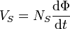 where VS is the instantaneous voltage, NS is the number of turns in the secondary coil and Φ equals the magnetic flux through one turn of the coil. If the turns of the coil are oriented perpendicular to the magnetic field lines, the flux is the product of the magnetic field strength B and the area A through which it cuts. The area is constant, being equal to the cross-sectional area of the transformer core, whereas the magnetic field varies with time according to the excitation of the primary. Since the same magnetic flux passes through both the primary and secondary coils in an ideal transformer the instantaneous voltage across the primary winding equals

Taking the ratio of the two equations for VS and VP gives the basic equation for stepping up or stepping down the voltage
- The main elements of the transformer are as below:
1) Magnetic circuit: limbs, yokes
2) Electrical circuit: primary secondary and tertiary windings, formers,
insulation and bracing devices.
3) Terminals, tappings, tapping switches, terminal insulators
4) Tank oil, cooling devices, conservators, dryers
- Special alloy steel of high resistance and low hysteresis loss is used as transformer core, CRGO steel.
- Cut the transformer sheets as far as possible along the grain which is the direction in which the material has a higher permeability
- For a large three-phase transformer, the core is a five-limbed core, which needs a cross-section in the yokes less than that required in the usual three-limbed core but core losses increase.

- On account of the easier insulation facilities, the low voltage winding is placed nearer to the core in the case of core type and on the outside positions in the case of shell type transformers.
- Cylindrical concentric helix windings are commonly employed for core-type transformers.
- Cross-over coils are suitable for currents not exceeding about 20A. They are used for HV windings in comparatively small transformers and comprise wires of small circular sections with double cotton covering
- Disc coils are made up of a number of flat sections, generally with rectangular wire
- In Disc coils, every turn is contact with oil hence better cooling
- Sandwich windings, commonly employed for shell-type transformers, allow for easy control over reactance.
- Bushings are the porcelain insulators used to provide insulation between conductor end terminals and the whole part of the T/F.
- Conservators are required to take up the expansion and contraction of the oil with changes of temperature in service without allowing the oil to come in contact with air.
- Breather extracts moisture from the air. It consists of calcium chloride or silica gel.
- Transformer oil serves the double purpose of cooling and insulating.
- Sludging is the slow formation of semi-solid hydrocarbons, sometimes of an acidic nature, which is deposited on windings and tank walls. The formation of sludge is due to heat and oxidation.
- Sludge formation is more in the presence of bright copper surfaces.
Losses & Efficiency in a Transformer
Losses in Transformer
Loss in any machine is when your output is lesser than the input you gave. In the transformer, this is a loss is in terms of power. As it is a static device, there are only electrical losses in a transformer, unlike a motor which also has mechanical losses. All types of losses are:
(a) Core Losses or Iron Losses
Losses occur in the core of the transformer. These are:
Hysteresis loss in transformer: Hysteresis loss occurs when there is a reversal in the process of magnetization in the transformer core. This loss depends upon the volume and grade of the iron, the value of flux density, and the frequency of magnetic reversals.
Eddy Current Loss in transformer: In the transformer, AC current is supplied to the primary winding which sets up alternating magnetizing flux. When this flux links with a secondary winding, it produces induced emf in it. But some part of this flux also gets linked with other conducting parts like steel core or iron body, which results in induced emf in those parts, resulting in small circulating currents in them. This current is called Eddy current. Due to these eddy currents, some energy is dissipated in the form of heat causing Eddy current loss in the transformer.
(b) Copper Loss
Copper loss occurs due to the resistance of the windings of the transformer. For primary winding, it is I12R1 and for secondary winding, it is I22R2 where I1 is primary current, R1 is primary winding resistance, I2 is secondary current and R2 is secondary winding resistance. As you can see, a Copper loss is directly proportional to the square of current and current depends on load, it implies that copper loss varies with the load connected to the transformer.
Efficiency of Transformer
Efficiency is given by the ratio of output power to input power.
Transformers are the most highly efficient electrical machines. Most of the transformers have full load efficiency between 95% to 98.5%.
Due to high efficiency, the output is nearly equal to the input power, so it becomes impractical to measure efficiency using a ratio of output and input. So a better way is to calculate the losses, subtract them from the input and then calculate the ratio.
Efficieny = Input – Losses / Input
Objective Questions:
1) Sludge formation in transformer oil is due to which one of the following?
a. Ingress of dust particles and moisture in the oil.
b. Appearance of small fragments of paper, varnish, cotton, and other organic materials in the oil
c. Chemical reaction of transformer oil with the insulating materials
d. Oxidation of transformer oil
Ans: d
Explanation: Refer above theory
2) Cores of large power transformers are made from which one of the following?
a. Hot-rolled steel
b. Cold-rolled non-grain oriented steel
c. Cold-rolled grain-oriented steel
d. Ferrite
Ans: c
Explanation: to increase the relative permeability
3)The function of oil in a transformer is to provide. Insulation and cooling
b. Protection against lightning
c. Protection against short circuits
d. Lubrication
Ans: a
Explanation: Refer above theory
4)Consider the following statements relating to the constructional features of a large power transformer:
1. The conservator is used to maintain the level of oil in the transformer tank
2. The bushing is used to protect transformer insulation against lightning over-voltages
3. The Buchholz relay is an over-current relay
4. Silica gel is used to absorb moisture.
Which of these statements is correct?
a. 1, 2, 3 and 4
b. 2 and 3
c. 1 and 4
d. 1, 2 and 4
Ans: c
Explanation: Refer above theory
5) In a large power transformer, a “conservator” drum is provided above the tank and connected to it by a short pipe. The conservator drum is linked to external air through a breather. What is the purpose of providing the conservator?
a) To store reserve oil to make up for oil losses due to leakage.
b) To prevent explosion due to a rise in oil pressure inside the tank during a fault.
c) To accommodate changes in oil level during the “load cycle” of the transformer load
d) To exert additional pressure by the conservator oil inside the main tank to prevent the disintegration of oil at high temperatures.
Ans: c
Explanation: Refer above theory
6)Match List I (Type of Coil) with List II (Use of Coil) and select the correct answer using the code given below the lists: List I
A. Sandwich coils
B. Disc coils
C. Cross-over coils
D. Spiral type
List II
1. Low voltage coils for currents above 100 A
2. High voltage windings of small transformers
3. Cooling oil is in contact with each turn of the winding
4. Shell-type transformer core
Codes;
A B C D
a. 2 3 4 1
b. 4 1 2 3
c. 2 1 4 3
d. 4 3 2 1
Ans: b
Explanation: Refer above theory
7) Assertion(A): For obtaining improved magnetic properties, the transformer magnetic core is assembled using cold-rolled silicon steel sheets.
Reason(R): The laminations for the core could be cut out of the cold rolled
silicon steel sheets, cutting either in the direction of rolling or transverse
thereof, without affecting the magnetic properties in any way.
a) Both A and R are individually true and R is the correct explanation of A
b) Both A and R are individually true but R is not the correct explanation of A
c) A is true but R is false
d) A is false but R is true
Ans: c
Explanation: Refer above theory
8) Assertion(A): Transformer is not used in a D.C. line
Reason(R): Losses in the Dc circuit are not negligible
a) Both A and R are individually true and R is the correct explanation of A
b) Both A and R are individually true but R is not the correct explanation of A
c) A is true but R is false
d) A is false but R is true
Ans: b
Explanation: Both are true. R is not a reason to A. because when T/F operates on the Dc line it burns.
9) Match List I with List II and select the correct answer using the code given below the lists:
List I
A. Silica gel
B. Porcelain
C. Mercury
D. Fins
List II
1. Bushing
2. Buccholz relay
3. tank
4. Breather
Codes;
A B C D
a. 2 1 4 3
b. 4 3 2 1
c. 2 3 4 1
d. 4 1 2 3
Ans: d
Explanation: Refer above theory
10) When are eddy current losses in a transformer reduced?
a. if laminations are thick
b. if the number of turns in the primary winding is reduced
c. if the number of turns in the secondary winding is reduced
d. if laminations are thin
Ans: d
Explanation: Pe=ke*f^2*B^2*t^2

