In Very Simple words.
The transformer is a device that:
- Transfer Electrical power from one electrical circuit to another Electrical circuit.
- It’s working without changing the frequency.
- Work through on electric induction.
- When both circuits take effect of mutual induction.
- Can’t step up or step down the level of DC voltage or DC Current.
- Can step up or step down the level of AC voltage or AC Current.
Component
- primary coil
- a set of insulated wires attached to the input current.
- iron core
- the conduit for the changing magnetic field.
- secondary coil
- a set of insulated wires attached to the output current.
The primary and secondary coils both have winding turns which will vary in number with respect to each other depending on the type of transformer.
Types
- step-up transformer
- The secondary coil has more turns than the primary coil (Ns > Np)
- step-down transformer
- The secondary coil has less turns than the primary coil (Ns < Np)
Transformers basics
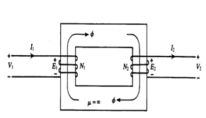
- The physical basis of a transformer (T/F) is mutual induction between two circuits linked by a common magnetic field. It is a static device.
- Mutual inductance is the same irrespective of which circuit is primary and which circuit is secondary.
- The voltage applied to the primary is almost completely concerned with opposing the induced e.m.f.
- If the primary voltage is constant, the mutual flux remains approximately constant regardless of the load connected across the secondary coil.
- Important tasks performed by T/F are
1) Changing voltage and current levels in the power system.
2) Matching source and load impedance for maximum power transfer
3) Electrical isolation
- In the core type, to avoid leakage flux, it is usual to have half the primary and half of the secondary winding side-by-side or concentrically on each limb; not primary on one limb and secondary on other limbs.
- In the three-phase core type, the principle that the sum of the fluxes in each phase in a given direction along the cores is zero.
- In core type inspection of coils and core is easy.
- The shell type is more robust mechanically.
- In shell type core, the cooling is good.
- The e.m.f induced in transformer given by: E = 4.44fΦmT volts
- Volt/turn is the same in the primary winding and secondary winding provided only that it links the same flux in both windings.
- Both primary and secondary e.m.f.’s are in phase.
- The e.m.f lag by 90 degrees in time on the flux.
- The applied voltage V1 opposes E1, while E2 provides the secondary output voltage V2.
- E1/E2 = I2/I1 = T1/T2
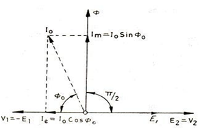
- A small magnetizing current is needed to maintain the magnetic circuit or core in the magnetized state when the secondary is open
- The m.m.f. of the primary on no load is of the order of 5 percent of its m.m.f. on full load.
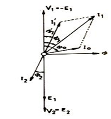
- The no-load current, Io has two components, magnetizing component, Im, and a loss component, Ir.
- Leakage between primary and secondary could be eliminated if the winding could be made to occupy the same space.
- Reductions in leakage flux can achieve by sectionalizing and interleaving the primary and secondary coils.
- An equivalent circuit is useful for calculations of regulation, efficiency, parallel operation, etc.
- I2R loss and per-unit reactance voltage in primary and secondary are the same.
- Core loss due to the pulsation of the magnetic flux in the iron-producing eddy current and hysteresis loss.
- I2R loss due to heating of the conductors by the passage of current.
- Stray loss due to the stay magnetic field causing eddy currents in the conductors or in surrounding metal (tank).
- Dielectric loss in the insulating materials (oil and solid insulation of HT T/F).
- The efficiency of a transformer is given by:
- Where S is full load kVA, x is per-unit load, Pi is iron loss, and Pc is full load copper loss.
- Maximum efficiency occurs when the variable loss is equal to the constant loss, i.e. x2 Pc= Pi.
- Maximum efficiency occurs below full load.
- Maximum efficiency point independent of power factor.
- The regulation of a transformer refers to the change of secondary terminal voltage between no-load and load conditions: it is usually quoted as a percent value for full load at a given power factor.
- Per unit regulation:
- Maximum regulation occurs when

- Zero regulation occurs when

i.e. leading p.f.
- On account of the easier insulation facilities, the low-voltage winding is placed nearer to the core in the case of core type and on the outside positions in the case of shell-type transformers.
- Under no-load conditions, the developed by energized power transformer originates in the core, where the lamination tends to vibrate by magnetic forces
- The essential factors in noise production are magnetostriction and mechanical vibrations by the lamination.
- In an Ideal transformer, there are no voltage drops in resistance or leakage reactance, the MMF required to maintain the main flux is small and there are no core losses.
- Magnetizing MMF is a function of the length, the net cross-sectional area, and the permeability of the iron path.
Objective Questions:
1) If the applied voltage of a certain transformer is increased by 50% and the frequency is reduced to 50% (assuming) that the magnetic circuit remains unsaturated), the maximum core /flux density will. Change to three times the original value
b. Change to 1.5 times the original value
c. Change to 0.5 times the original value
d. Remain the same as the original value
Ans: d
Explanation: B∝ V/f
2). In a transformer, zero voltage regulation at full load is
a. not possible
b. possible at leading power factor load
c. possible at lagging power factor load
d. possible at unity power factor load
Ans: b
Explanation:
- Zero regulation occurs when
i.e. leading pf.
3). The full load copper loss and iron loss of a transformer are 6400W and 500W respectively. The above copper loss and iron loss at half load will be
a) 3200 W and 250 W respectively
b) 3200 W and 500 W respectively
c) 1600 W and 125 W respectively
d) 1600 W and 500 W respectively
Ans: d
Explanation: Refer above theory
Pcu=x2*Pcu.fl=(0.5)2*6400=1600W
Pi=500W ( independent of the load)
4). A 4KVA, 400V/200V single-phase transformer has a resistance of 0.02 ohm and a reactance of 0.06 ohm. The resistance and reactance referred to high voltage side are
a) 0.2 Ω and 0.6 Ω
b) 0.8 Ω and 2.4 Ω
c) 0.08 Ω and 0.24 Ω
d) 1 Ω and 3 Ω
Ans: c
Explanation: R2+jX2=0.02+j0.06
a=V2/V1=200/400=0.5
R2’+jX2’=(R2+jX2)/(a2)=0.08+j0.24
5). A single-phase transformer rated for 220/440 V, 50 Hz operates at no load at 220 V, 40Hz. This frequency operation at rated voltage results in which one of the following?
a. Increases of both eddy-current and hysteresis losses
b. Reduction of both eddy-current and hysteresis losses
c. Reduction of hysteresis loss and increase in eddy-current loss
d. Increase of hysteresis loss and no change in the eddy-current loss
Ans: d
Explanation: Ph=kh*f*Bx; B∝ V/f hysteresis loss increases with a decrease in frequency.
Pe=ke*f^2*B^2*t^2, B∝ V/f eddy current loss depends on the square of the applied voltage and is independent of the frequency.
6). What is the load at which maximum efficiency occurs in the case of a 100 kVA transformer with iron loss of 1 kW and full–load copper loss of 2 kW?
a. 100 kVA
b. 70.7 kVA
c. 50.5 kVA
d. 25.2 kVA
Ans: b
Explanation: Pcu*x2=Pi; x=sqrt(Pi/Pcu)= sqrt(1/2);
load KVA=100*x=100*sqrt(1/2)=70.7 KVA
7). Cores of large power transformers are made from which one of the following?
a. Hot-rolled steel
b. Cold-rolled non-grain oriented steel
c. Cold-rolled grain-oriented steel
d. Ferrite
Ans: c
Explanation: to increase the relative permeability
8). A transformer has a percentage resistance of 2% and a percentage reactance of 4%. What are its regulations at power factor 0.8 leading, respectively?
a. 4% and – 0.8%
b. 3.2% and – 1.6%
c. 1.6% and – 3.2 %
d. 4.8% and – 0.6%
Ans: a
Explanation: Per unit regulation:
%regulation, lagging = 2*0.8+4*0.6= 4%
%regulation, leading = 2*0.8-4*0.6= -0.8%
9) Assertion(A): Both the efficiency and regulation of a 3-winding ideal
transformer are 100%
Reason(R): The flux leakage and the magnetic reluctance of the magnetic core
in an ideal transformer is zero. moreover, losses are absent in ideal
transformers
a) Both A and R are individually true and R is the correct explanation of A
b) Both A and R are individually true but R is not the correct explanation of A
c) A is true but R is false
d) A is false but R is true
Ans: d
Explanation: Ideal transformer has 100% efficiency and 0% regulation
10) When are eddy current losses in a transformer reduced?
a. if laminations are thick
b. if the number of turns in the primary winding is reduced
c. if the number of turns in the secondary winding is reduced
d. if laminations are thin
Ans: d
Explanation: Pe=ke*f^2*B^2*t^2
11) on which of the following factors does hysteresis loss depend?
1. flux density
2. frequency
3. thickness of the lamination
4. time
select the correct answer using the codes given below.
a) 2 and 3 a) 1 and 2 a) 3 and 4 a) 1 and 4
Ans: d
Explanation: Ph=kh*f*B^x;
12) If P1 and P2 are the iron and copper losses of a transformer at full load, and the maximum efficiency of the transformer is at 75% of the full load, then what is the ratio of P1 and P2?
a. 9/16
b. 10/16
c. 3/4
d. 3/16
Ans: a
Explanation: Pcu*x^2=Pi; x=0.75=3/4; P1/P2=Pi/Pcu=x^2= (3/4)^2=9/16;
13). If the iron core of a transformer is replaced by an air core, then the hysteresis losses in the transformer will
a. increase
b. decrease
c. remain unchanged
d. become zero
Ans: d
Explanation: air core transformer is free from hysteresis loss
14). The equivalent circuit of a transformer has the leakage reactance X1, X ‘2 and the magnetizing reactance Xm. What is the relationship between their magnitudes?
a. X1 >> X’2 >> Xm
b. X1 << X’2 << Xm
c. X1≈ X2 >> Xm
d. X1≈ X’2 << Xm
Ans: d
Explanation: Xm is a parallel circuit in the equivalent circuit
16). If the voltage applied to a transformer primary is increased by keeping the V/f ratio fixed, then the magnetizing current and the core loss will, respectively,
a. decrease and remain the same
b. increase and decrease
c. remains the same and remains the same
d. remains the same and increase
Ans: d
Explanation: Im ∝ V/f; Im unchanged and core loss depends on the frequency so increases.
17) The use of higher flux density in the transformer design
a. Reduces the weight per kVA
b. Increases the weight per kVA
c. Has no relation with the weight of transformer
d. Increases the weight per kW
Ans: a
Explanation: B=Φ/A . for the same Φ, A is less. so the weight will reduce
18) The function of oil in a transformer is to provide
a. Insulation and cooling
b. Protection against lightning
c. Protection against short circuits
d. Lubrication
Ans: a
Explanation: Insulation and cooling
19)A single-phase transformer when supplied from 220 V, 50 Hz has an eddy current loss of 50 W. If the transformer is connected to a voltage of 330V, 50 Hz, the eddy current loss will be
a. 168.75 W
b. 112.5 W
c. 75W
d. 50W
Ans: b
Explanation: Pe=ke*f^2*B^2*t^2, B∝ V/feddy current loss depends on the square of the applied voltage and is independent of the frequency.
Pe2/Pe1=(V2/V1)^2= (330/220)^2=2.25;
Pe2=50*2.25=112.5 W
20) Match List I with List II and select the correct answer:
List I
A. Shell type with a wound core
B. Core type with a core of laminated sheets
C. Shell type with a laminated core
D. Core type with a wound core
List II
A B C D
a. 4 3 1 2
b. 4 2 1 3
c. 1 2 4 3
d. 1 3 4 2
Ans: b
Explanation: Refer above theory


