
Working Principle of a Three-Point Starter
A three-point starter is a device used to start a three-phase induction motor. It is a type of manual starter that uses three points of contact to control the flow of electrical current to the motor. The three points of contact are typically labeled as “R”, “S”, and “T” and correspond to the three phases of the motor.
The working principle of a three-point starter is as follows:
- When the starter handle is moved to the “R” position, the “R” contact is closed, allowing current to flow through the “R” phase of the motor.
- When the starter handle is moved to the “S” position, the “S” contact is closed, allowing current to flow through the “S” phase of the motor.
- When the starter handle is moved to the “T” position, the “T” contact is closed, allowing current to flow through the “T” phase of the motor.
- When all three contacts are closed, the current flows through all three phases of the motor, creating a rotating magnetic field that causes the rotor to turn and start the motor.
It’s important to note that the three-point starter is not a device used in modern systems, it was common in the past, but now it has been replaced by other types of starters such as the Direct-on-Line (DOL), Star-Delta, and Auto Transformer starters.
The three-point starter has the disadvantage of being bulky and not very reliable, also it required manual operation and manual phase selection, which can be dangerous if the operator makes an error.
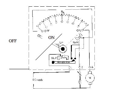
Three-Point Starter Measuring instruments
• The above figure shows, the motor is connected to supply terminals through three terminals L, A, and F available in the starter, it is called a three-point starter.
• In this starter the resister elements are mounted behind an insulating board.
• The end of the resistor elements meet at the brass studs fixed on the front side of the board.
• The handle of the starter is fixed to a point so as to be moved over the studs against spring tension.
• When the starter handle is moved and makes contact with the first stud full voltage is applied to a series combination of resistor elements and armature.
• Therefore a reduced voltage is applied to the armature due to a drop in the resistor elements and starting current is limited to a safe value.
• At the same time full voltage is applied across the shunt field and this establishes normal flux.
• As the starter handle is moved towards the right from one stud to the next stud the resistor elements are cut out one by one and the voltage applied to the armature increases step by step.
• Finally when all the resistance elements are cut out the handle is in one position and full voltage is applied across the armature terminals.
• Now the current flowing through the no-volt release coil develops an attractive force over the soft iron piece fixed to the starter handle.
• At normal voltage this attractive force holds the handle in on position against the spring tension at the pivoted end of the handle.
• When the applied voltage falls below a certain value or at the interruption of supply voltage, the attractive force developed at the no-volt release coil over the handle may not be sufficient to keep the handle in on position against the spring tension.
• Therefore the handle flies back to the off position immediately and avoids restarting the motor on resumption of supply.
• If such arrangement is not there in the starter and the handle is on position, on resumption of supply full voltage would be applied to the armature terminals.
• Also, the voltage release coil is connected in series with the shunt field, and the starter handle is released to off position whenever the field circuit is opened.
• This avoids racing or motor to high speed.
• The overload relay is connected in series with the armature circuit and carries load current.
• When a motor has overloaded the current through the overload relay increases. If this current exceeds a predetermined value, the mmf produced by the overload coil lifts the pivoted iron piece underneath the coil.
• This iron piece short circuits the no voltage release coil and destroy its attractive force over the handle.
• Therefore the handle is released to off position.
• When the handle is moved to the right and resistance elements are cut out, they are in turn, included in the field circuit.
• Since the resistance of these elements is very small, their inclusion of them in the field circuit does not affect the field current appreciably.
• Another important point is that the armature and shunt field circuits are closed against each other through the starting resistor element even when the handle is in off position.
• Therefore the energy stored in the magnetic circuit gets dissipated slowly through starting and armature resistances.
• Thus inductance is avoided.
Related Topic – click here
- Dynamometer Type Three-Phase Wattmeter
- Three Methods Of Compounding In Steam Turbines
- Classification Of Moving Iron Instruments
- CONSTRUCTION OF D.C. MACHINE
- Three-Point Starter Measuring Instruments
- Electrodynamometer (Electrodynamics) Type Instruments
- STATIC & DYNAMIC CHARACTERISTICS OF ELECTRICAL MEASUREMENT SYSTEM
- Starting Of Induction Motor | Types Of Three-Phase Induction Motor Starting Methods
- Electrical Engineering History Facts Words | History Of E
