
Three-phase induction motor
Three-phase induction motor an induction motor is simply an electric transformer whose magnetic circuit is separated by an air gap into two relatively movable portions, one carrying the primary and the secondary winding.
Three-phase induction motor ppt alternating current supplied to the primary winding from an electric power system includes opposing currents in the secondary winding.
when the latter is short-circuited or closed through an external impedance. Relative motion between the primary and secondary structure is produced by the electromagnetic forces corresponding to the power thus transferred across the air gap by three-phase induction motor construction and working principle.
Construction of induction motor the essential feature which distinguishes the induction machine from other types of electric motor is that the secondary currents are created solely by induction, as a transformer instead of being supplied by a D.C. exciter or other external power source, as in synchronous and D.C. machines.
working principle of 3 phase induction motor
The working principle of a 3-phase induction motor is based on the principle of electromagnetic induction. When a three-phase AC voltage is applied to the stator windings, a rotating magnetic field is created. The rotor, which is made up of a cage of conductors, is located within this rotating magnetic field. The rotating magnetic field induces an electromotive force (EMF) in the rotor conductors, causing them to rotate and turn the motor shaft.
As the rotor rotates, it also induces an EMF in itself which is known as the induced EMF. The induced EMF in the rotor is always less than the stator EMF due to the difference in the speed between the stator and rotor field. To overcome this difference and to make the rotor rotate at the same speed as the stator field, the rotor is made to draw current from the stator winding which is known as the rotor current. This current flowing through the rotor winding creates its own magnetic field which is always in quadrature with the stator field. This interaction between stator and rotor magnetic field causes the rotor to rotate at the same speed as the stator field. This is known as the “rotating magnetic field” principle.
Advantages
Three-phase induction motor is the most commonly used motor in industrial applications because of the advantage listed below.
- Simple design
- Rugged construction
- Reliable operation
- Low initial cost
- Easy operation and simple maintenance
- High efficiency
- Simple control gear for starting and speed control.
Application
Induction motors are available with torque characteristics suitable for a wide variety of loads.
- The standard motor has a starting torque of about 120 to 150 percent of full-load torque. such motors are suitable for most applications.
- For starting loads such as small refrigerating machines or plunger pumps operating against full pressure or belt conveyors, high torque motors with a starting torque of twice normal full-load torque, or more, are used.
- For driving machines that use large flywheels to carry peak loads, such as punch presses and shears, a high-torque motor with a slip at full load up to 10 percent is available. The high slip permits enough charge in speed to make it possible to obtain any value of starting torque up to the maximum breakdown torque.
- By the use of a wound rotor with suitable controlled and external resistance connected in series with the rotor winding, it is possible to obtain any value of starting torque up to the maximum breakdown torque. Such motors are well-adapted constant-speed drives for loads that have large friction loads to overcome starting.
Classification of A.C. motors
1. According to the type of current.
- Single-phase
- Three-phase
2. According to speed.
- Constant speed
- Variable speed
- Adjustable speed
3. According to the principle of operation
- Plain
- super
4. According to structural features
- Open
- Enclosed
- Semi-enclosed
- Ventilated
- Pipe-ventilated
- Riveted frame eye
- Splash proof
- Totally enclosed fan-cooled
- Explosion-proof
- Waterproof
Constructional Details
The stator
Construction of stator of induction motor the stator frame consists of a symmetrical and substantial casting, having feet cast integral with it. The stator core, consisting of high-grade, low-loss electrical sheet-steel stampings, is assembled in the frame with hydraulic pressure.
The thickness of stamping laminations is usually from 0.35 to 0.6 mm. The stator laminations are punched in one piece for a small induction motor. In an induction machine of large size, the stator core is assembled from a large number of segmental laminations.

The stator winding is given the utmost care to make them mechanically and electrically sound, so as to ensure long life and high efficiency. After the winding is in a position it is thoroughly dried out whilst still hot and is completely immersed in a high-grade synthetic resin varnish. It is acid, alkali, moisture, and oil-proof.
For small motor working at ordinary voltages, a single layer much winding is used. For medium size machines, double-layer lap winding with diamond-shaped coils is used. Single-layer concentric windings are used for large motors working at high voltages.
Frames of electrical machines house the starter core. Frames of small and medium sizes of induction motors have hollow cylindrical from and that of large motors have the shape of a circular box. In small induction motors.
Having a frame diameter of up to about 150 cm, the frame also supports the end shields. The frame should be strong and rigid as rigidity is very important in the case of induction motors of large dimensions.
This is because the length of the air gap is very small and if the frame is not rigid, it would create an irregular air gap around the machine resulting in the production of an unbalanced magnetic pull.
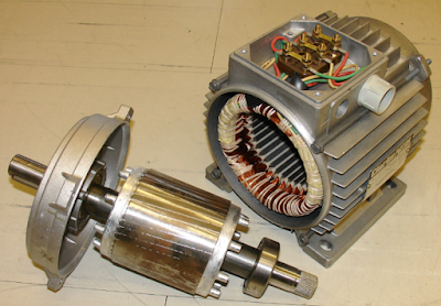
The Rotor

The rotors are of two types
1. Squirrel-cage
The squirrel-cage rotor is made up of stampings that are keyed directly to the shaft. The slots are partially closed and the winding consists of embedded copper bars t which squirrels rotor the short-circuited rings are brazed.
The squirrel cage rotor is so robust that it is almost indestructible. The gear majority of present-day induction motors are manufactured with squirrel cage rotors a common practice being to employ winding of cast aluminum is forced in under pressure.
It forms bars, end rings, and cooling fans as die-cast rotors and has become very popular as there are no joints and thus there is no possibility of high contact resistance.
2. Wound rotor
The wound rotor has also slotted stampings and the windings are formed wound. The wound rotor construction is employed for induction motors requiring speed control or extremely high value of starting torque.
The wound rotor has completely insulated copper windings very much like the stator windings. The windings can be connected in a star or delta and the three ends are brought out at the three slip rings.
The current is collected from these slip rings with carbon brushes from which it is led to the resistance for starting purposes.
When the motor is running, the slip rings are short-circuited by means of a collar, which is pushed along the shaft and connects all the slip rings together on the inside.
Usually, the brushes are provided with a device for lifting them from the slip rings when the motor has started up, thus reducing the wear and frictional losses.
The number of slots in the rotor should never be equal to the number of slots in the stator If they are, there would be a variation of the reluctance of the magnetic path from maximum, when teeth are opposite slots, to a minimum when teeth are opposite teeth.
The resulting flux pulsations would have a high frequency since the periodic time would be the interval period for a tooth to occupy similar positions opposite two successive teeth. This will not only cause extra ions loss but the rotor will tend to lock with the stator if at the time of starting teeth are opposite teeth. The best plan is to make the number of the stator and the rotor teeth prime to each other.
What is the operating principle of a 3-phase induction motor?
A 3-phase induction motor operates on the principle of electromagnetic induction. The stator, or stationary part of the motor, consists of three windings arranged in a “Y” configuration. When a three-phase AC voltage is applied to the stator windings, a rotating magnetic field is created. The rotor, or rotating part of the motor, is made up of a cage of conductors that are subject to the rotating magnetic field. This induces an electromotive force (EMF) in the rotor conductors, causing them to rotate and turn the motor shaft. This is known as the “rotating magnetic field” principle.
Related Topic – click here
- What Is A Diode? Working Principle & Types | Different Types Of Resistors
- What Is Synchronous Speed? | Types & Advantages Of DC Motors
- Working Principle Of Linear Variable Differential Transformer | Construction & Piezoelectric Transducers
- Three-Phase Induction Motor | 3-Phase Induction Motor Principle
- Introduction To Electrical Transformer | Definition, Construction & Parts Of A Transformer | Types Of Transformers
- DC Generator | Principle Of Operation, Construction, Types Of Generators & Application
- What Is DC Motor? | Principle Of DC Motor & Types Of DC Motors
- Diode-Circuits |Diode Convention, Transformer Rectifier & Objective Questions With Answer

