
Synchronous speed
There are two ways to define motor speed. First is synchronous speed. The synchronous speed of an AC motor is the speed of the stator magnetic field rotation. This is the motor’s theoretical speed since the rotor will always turn at a slightly slower rate.
The other way motor speed is measured is called actual speed. This is the speed at which the shaft rotates. The nameplate of most AC motors lists the actual motor speed rather than the synchronous speed.
Standard AC induction motors depend on the rotor trying, but never quite succeeding, to catch up with the stator’s magnetic field. The difference in the speed of the rotor and the synchronous speed of the stator’s rotating magnetic fields is called the slip. Different motor designs will produce different amounts of slip.
AC motors are designed with various numbers of magnetic poles. Standard motors have two, four, six, or eight poles. These poles play an important role in determining the synchronized speed of an AC motor.
A motor’s synchronous speed can be computed using this formula: synchronous speed equals 120 times the operating frequency, divided by the number of poles.

For example, A six-pole motor’s synchronous speed is 120 x 60 = 7200 divided by 6, or 1200 RPM.
A four-pole motor’s synchronous speed will be 1800 RPM. Use this formula to determine other speed/pole relationships.
Types of DC Motors
Shunt Wound DC Motors
Shunt wound DC motors provide medium starting torque, 125% to 200% full load, and are capable of delivering 300% of full load torque for short periods. With excellent speed control, shunt wound motors generally drive loads requiring speed control and low starting torque.
Some applications include fans, blowers, centrifugal pumps, conveyors, elevators, printing presses, woodworking machines, and metalworking machines.
There are two basic types of shunt wound DC motors. Self-excited shunt wound motors have a shunt field and armature connected to the same power supply.
In separately excited shunt wound motors, the shunt field and armature connect to separate power supplies.
Series Wound DC Motors
A series-wound DC motor has its armature and field connected in a series circuit. These types of motors normally drive loads that require high torque and do not require precise speed regulation. Series DC motors are ideal for traction work where the load requires a high breakaway torque. Such are locomotives, hoists, cranes, automobile starters, or oil drilling rig applications.

Starting torque developed in series motors normally ranges between 300% and 375% of full load but attains 500% of full load torque. These motors deliver this high starting torque because their magnetic field operates below saturation.

An increase in load results in an increase in both armature and field current. As a result, the armature flux and field flux increase simultaneously. Since the torque developed in DC motors is dependent upon the interaction of armature and field flux, torque increases by the square of current increase.
Speed regulation in series motors is inherently less precise than in shunt motors. If the motor load diminishes, the current flowing in both the armature field circuits reduces as well, affecting a reduction in flux density.
This results in a greater increase in speed than realized in shunt motors. Removal of mechanical load from series motors results in indefinite speed increase whereby centrifugal forces generated by the armature eventually destroy the motor.
Compound Wound DC Motors
Whenever an operation requires speed regulation characteristics unavailable in series or shunt motors, compound wound motors perform well. With medial starting torque capability, between 180 and 260% of full load, they deliver constant operating speeds under any percentage of full load.
Fig. Permanent Magnet DC Motors
This characteristic is a result of placing part of the field circuit in series with that of the armature. When under load, increased series winding current raises the level of field flux. Enlarged field flux in compound wound motors yields a greater reduction in speed than in a shunt motor.

The compound wound DC motor comprises both series and shunt windings. The shunt winding connects in parallel with the armature and series windings. Some associated applications include punch presses, shears, crushers, and reciprocating compressors.
Permanent Magnet DC Motors
Permanent magnet motors are well fit for use where response time is a factor. Their speed characteristics are similar to those of shunt wound motors. Built with a conventional armature, they use permanent magnets rather than windings in the field section. DC power is supplied only to the armature.
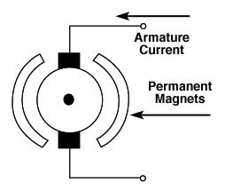
Permanent magnet motors are not expensive to operate since they require no field supply. The magnets, however, lose their magnetic properties over time, and this affects less-than-rated torque production. Some motors have windings built into the field magnets that re-magnetize the cores and prevent this from happening.

Automobiles have installed DC permanent magnet motors that control power seats, windows, and windshield wipers. DC permanent magnet motors produce high torque at low speeds and are self-braking upon disconnection of electrical power. Permanent magnet motors cannot endure continuous operation because they overheat rapidly, destroying the permanent magnets.
Universal DC Motors
Universal motors seldom exceed one horsepower and do not run at constant speeds. The speed of a universal motor varies with its load. Among the applications using these motors are vacuum cleaners, food mixers, portable drills, portable power saws, and sewing machines.
In most cases, little more than a few hundred rpm is reached with heavy loads. When the motor operates with no load, the speed may attain 15,000 rpm.
The universal series motor differs in design from a true induction motor. The rotor of a universal motor is made of a laminated iron wound with wire coils. The ends of the coils, or loops, connect to a commutator. The electric current in the motor flows through a complete circuit formed by the stator winding and rotor winding. Brushes ride on the commutator and conduct the current through the rotor from one stator coil to the other. Directed by these brushes the rotor current interacts with the magnetic field of the stator causing the rotor to turn. When the direction of the current flow changes in the stator, it changes in the rotor. Since the magnetic field is reversed, the rotor continues to turn.
Universal motors have series wound rotor circuitry similar to that of DC motors. They have high starting torque and high starting current. The name universal derives from the motor’s capability of operating on either AC or DC power sources.
Universal, variable-speed motors slow down with increased loads. A high horsepower-to-size ratio is characteristic of their design. Due to the brush/commutator setup, universal motors require more maintenance than other motor designs.
DC Motor
Advantages of DC Motors
DC motors provide excellent speed control for acceleration and deceleration with effective and simple torque control. The fact that the power supply of a DC motor connects directly to the field of the motor allows for precise voltage control, which is necessary with speed and torque control applications.
DC motors perform better than AC motors on most traction equipment. They are also used for mobile equipment like golf carts, quarries, and mining equipment. DC motors are conveniently portable and well suited to special applications, such as industrial tools and machinery that is not easily run from remote power sources
Synchronous motors are a type of AC electric motor that runs at a speed that is directly proportional to the power frequency. They have a number of advantages and disadvantages when compared to other types of motors.
Advantages of synchronous motors:
- High efficiency: Synchronous motors have a high power factor and high efficiency, which means they can convert more of the input energy into useful work.
- Constant speed: Synchronous motors run at a constant speed, regardless of the load on the motor. This makes them well-suited for applications that require precise speed control.
- Good power factor: Synchronous motors have a good power factor, which means that they consume less current and produce less heat than other types of motors for the same amount of power.
- Low-maintenance: Synchronous motors are relatively low-maintenance as compared to other types of motors.
Disadvantages of synchronous motor
Disadvantages of synchronous motors:
- Cost: Synchronous motors are generally more expensive than other types of motors, such as induction motors.
- Requires power electronic devices: Synchronous motors require power electronic devices like AC-DC-AC converter or inverter to work.
- Requires excitation: Synchronous motors require a separate source of excitation to generate the magnetic field.
- Less starting torque: Synchronous motors have less starting torque as compared to induction motors, which makes them less suitable for applications that require a lot of starting torque.
Overall, synchronous motors are a good choice for applications where high efficiency, constant speed, and good power factor are required, but they are more expensive, require power electronic devices, and less starting torque as compared to other types of motors
Types of Motors
There are several kinds of DC motors commonly used in industrial applications. The motors have similar external appearances but are different in their internal construction and output performance. When selecting a DC motor for a given application, two factors must be taken into consideration:
1. The allowed variation in speed for a given change in load.
2 The allowed variation in torque for a given change in load.
DC Motors
Brushed DC motors
The classic DC motor design generates an oscillating current in a wound rotor, or armature, with a split ring commutator, and either a wound or permanent magnet stator. A rotor consists of one or more coils of wire wound around a core on a shaft; an electrical power source is connected to the rotor coil through the commutator and its brushes, causing current to flow in it, producing electromagnetism.
The commutator causes the current in the coils to be switched as the rotor turns, keeping the magnetic poles of the rotor from ever fully aligning with the magnetic poles of the stator field, so that the rotor never stops (like a compass needle does) but rather keeps rotating indefinitely (as long as power is applied and is sufficient for the motor to overcome the shaft torque load and internal losses due to friction, etc.)
Many of the limitations of the classic commutator DC motor are due to the need for brushes to press against the commutator. This creates friction. At higher speeds, brushes have increasing difficulty in maintaining contact.
Brushes may bounce off the irregularities in the commutator surface, creating sparks. (Sparks are also created inevitably by the brushes making and breaking circuits through the rotor coils as the brushes cross the insulating gaps between commutator sections.
Depending on the commutator design, this may include the brushes shorting together adjacent sections—and hence coil ends—momentarily while crossing the gaps. Furthermore, the inductance of the rotor coils causes the voltage across each to rise when its circuit is opened, increasing the sparking of the brushes.)
This sparking limits the maximum speed of the machine, as too-rapid sparking will overheat, erode, or even melt the commutator. The current density per unit area of the brushes, in combination with their resistivity, limits the output of the motor.
The making and breaking of electric contact also cause electrical noise, and the sparks additionally cause RFI. Brushes eventually wear out and require replacement, and the commutator itself is subject to wear and maintenance (on larger motors) or replacement (on small motors).
The commutator assembly on a large machine is a costly element, requiring the precision assembly of many parts. On small motors, the commutator is usually permanently integrated into the rotor, so replacing it usually requires replacing the whole rotor.
Large brushes are desired for a larger brush contact area to maximize motor output, but small brushes are desired for low mass to maximize the speed at which the motor can run without the brushes excessively bouncing and sparking (comparable to the problem of “valve float” in internal combustion engines). (Small brushes are also desirable for a lower cost.)
Stiffer brush springs can also be used to make brushes of a given mass work at a higher speed, but at the cost of greater friction losses (lower efficiency) and accelerated brush and commutator wear. Therefore, DC motor brush design entails a trade-off between output power, speed, and efficiency/wear.
There are four types of DC motors:
1. DC series motor
2. DC shunt motor
3. DC compound motor –
there are also two types:
(a) cumulative compound
(b) differentially
4. Permanent Magnet DC Motor
Related Topic – click here
- What Is A Diode? Working Principle & Types | Different Types Of Resistors
- What Is Synchronous Speed? | Types & Advantages Of DC Motors
- Working Principle Of Linear Variable Differential Transformer | Construction & Piezoelectric Transducers
- Three-Phase Induction Motor | 3-Phase Induction Motor Principle
- Introduction To Electrical Transformer | Definition, Construction & Parts Of A Transformer | Types Of Transformers
- DC Generator | Principle Of Operation, Construction, Types Of Generators & Application
- What Is DC Motor? | Principle Of DC Motor & Types Of DC Motors
- Diode-Circuits |Diode Convention, Transformer Rectifier & Objective Questions With Answer


