
Different Types of Substations Explained
SUBSTATION
As the power demand increases in this economical generation of electrical energy, it becomes more common to have bigger and bigger powerhouses. The powerhouses might be closer and might be far from the load center; in any case, it needs a transmission network.
In the midst of powerhouses and the consumer, many transformations need to be installed that transformation is called substation.
A substation is a system that converts one voltage level into another voltage level and mostly it converts 11kv into 415v.
Normally the user does not want high voltage i.e. 11kv, so it needs to be converted into 415v by the means of the substation, so we can say that substation is the link between the generating stations and the consumer main.
Our project is limited to an office building, so a distribution substation also needs to be considered. The distribution substation converts the voltage to a small value for the use of small power consumers. Generally, we use 3 phase 4-wire system for the distribution substation with 415v between the lines and 230v per phase.
i. DESIGN OF SUBSTATION
For the design of the substation, some important points need to be considered
- Ø It should be possible to have easy and safe access for the maintenance and inception of different equipment.
- Ø The layout of the substation should be such that when the fault comes into the power system it isolates the fault as quickly as possible.
- Ø By considering the capacity of the substation, number of feeders, etc layout of the switch gear is decided.
- Ø Power cable and control cable should be separate.
- Ø By considering the IP rating fire proof switch room and cable should be installed in order to be safe from fire hazards.
ii. EQUIPMENT USED IN SUBSTATION
The substation consists of the following equipment.
1-Insulators 2-Conductors 3-Reclosing and LT switchgear
4-Circuit breaker 5-Transformer 6-Protective fuses and relays
7-switch board 8- metering
1-INSULATORS
For the backing of the bus bars and live conductors insulators are used. For low voltages, up to 11kv insulators can be used in the stack and can be mounted horizontally and vertically as per condition but for low voltages beyond that, insulators are mounted mostly in a horizontal configuration.
2-CONDUCTORS
Conductors are of two types for the substation.
1- Rigid buses of solid conductors
2-Strain buses of cable
These types of conductors could be Aluminum and Copper.
3-RECLOSING AND LT SWITCHGEAR
A recloser is a circuit breaker equipped mechanism, that trip the breaker after it has been opened due to faulty. We use reclosers for the overhead distribution system reclosers are used on a low-voltage bus structure column. While, the switchgear is the combination of disconnect switches, fuses, and circuit breakers used to isolate the equipment in the substation. The distribution of current in various places depends on the number of outlets required.
4-CIRCUIT BREAKER
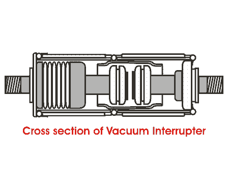
Mostly vacuum circuit breaker is used inside the building that’s why we used vacuum circuit breaker.
A vacuum circuit breaker is a type of circuit breaker where arcing occurs in a vacuum. This is normally used for medium voltage applications, for high voltage this technology was also developed but it is not common. The opening and closing of current-carrying contacts are associated with arc interruption which is taking place in a vacuum chamber of the breaker which is called a vacuum interrupter. The pressure of the vacuum is normally maintained at 10^-6 bars. The contacts are made up of cu and cr.
4.1-ADVANTAGES OF VACUUM CIRCUIT BREAKER
Ø Life of the vacuum circuit breaker is longer than the other type of circuit breakers.
Ø Chances of fire hazard are almost negligible.
4.2-OPERATION OF VACUUM CIRCUIT BREAKER
The task of any circuit breaker is to quench the arc during current zero crossing, by establishing high dielectric strength in between the contacts so that reestablishment of the arc after current zero becomes impossible. The dielectric strength of a vacuum is eight times greater than that of air and four times greater than that of SF6 gas.
This high dielectric strength makes it possible to quench a vacuum arc within a very small contact gap. For a short contact gap, low contact mass, and no compression of medium the drive energy required in a vacuum circuit breaker is minimum. When two face-to-face contact areas are just being separated from each other, they do not be separated instantly, the contact area on the contact face is reduced and ultimately comes to a point, and then they are finally de-touched. Although this happens in a fraction of a microsecond it is the fact.
At this instant of de-touching of contacts in a vacuum, the current through the contacts is concentrated on that last contact point on the contact surface and makes a hot spot. As it is a vacuum, the metal on the contact surface is easily vaporized due to that hot spot and creates a conducting media for the arc path. Then the arc will be initiated and continued until the next current zero. At current zero this vacuum arc is extinguished and the conducting metal vapor is re-condensed on the contact surface.
At this point, the contacts are already separated hence there is no question of re-vaporization of the contact surface, for the next cycle of current. That means, the arc cannot be reestablished again. In this way, the vacuum circuit breaker prevents the re-establishment of the arc by producing high dielectric strength in the contact gap after the current is zero.
There are two types of arc shapes. For interrupting current up to 10kA, the arc remains diffused and the form of vapor discharge covers the entire contact surface. Above 10kA the diffused arc is constricted considerably by its own magnetic field and it contracts.
The phenomenon gives rise to the heating of contact at its center. In order to prevent this, the design of the contacts should be such that the arc does not remain stationary but keeps traveling by its own magnetic field. The specially designed contact shape of the vacuum circuit breaker makes the constricted stationary arc travel along the surface of the contacts, thereby causing minimum and uniform contact erosion.
5-TRANSFORMER
The function of the transformer in the substation is to convert 11kv into 415v.in Pakistan mostly oil type transformer is used because of their large service life. Oil-type transformer requires minimum maintenance. The main factors which are need to be considered for the installation of transformers are
A- Initial costs
B- Operating costs
C- Reliability of supply
D- Served load
6-PROTECTIVE FUSES AND RELAYS
Normally fuses are provided with the transformer and other protective devices. Its function is to protect the transformer.
Protective relays are also provided for the safety of the power system. For the protection of the transformer, we use BUCHOLOZ RELAY.
When a fault occurs in a transformer or a short circuit occurs in the transformer then the pressure inside the oil tank increases and oil starts moving towards conservators in this passage it also passes through the BUCHOLZ RELAY. The baffles in the relay get passed by the rushing oil and now the relay will operate and accordingly it trips the circuit breaker. Now we can remove the transformer for the service.
7-SWITCH BOARDS
Meters, relays, and control equipment are placed in a switchboard. Two meters i.e. essential and nonessential are placed at the top of the relay and bottom of the relay respectively. The control equipment is normally placed half way between the top and bottom so as to facilitate their operation.
8-METERING
The energy meter incorporating maximum demand indicators is provided with the incoming HT supply. An ammeter and volt meter are also provided with the selector switch to shift across the lines are also fitted in the HT panel. An ammeter and the one-volt meter has been also provided with the LT lines.
Related topic – click here
- DC Machines – Types Of DC Motor | DC Motor Presentations
- Transducer Classification Of Transducers | Thermistors Application Of Thermistors
- Digital Electronics | Advantages And Disadvantages Of Digital Electronic | Digital Circuit
- What Are Semiconductor Devices? | Definition, Type, Conductor | Difference Between Semiconductors And Conductors Semiconductors
- Vector Groups Of Transformer | Application Of Transformer According To Vector Group
- DC GENERATOR | Principle, Types, & Applications
- ELECTRICITY POWER GENERATING STATION | Power Plants, Thermal Station & Hydroelectric Power Station
- RESONANT CIRCUITS | What Is Resonance?, Q-Factor
- DC Motors | Principles Of Operation Of DC Motor, Advantages Of DC Mo
