
Stepper Motors, Their Types, Construction And Applications Explained
Stepper Motor:
A stepper motor is an electromechanical device that converts electrical pulses into discrete mechanical movements. The shaft or spindle of a stepper motor rotates in discrete step increments when electrical command pulses are applied to it in the proper sequence. The motor’s rotation has several direct relationships to these applied input pulses. The sequence of the applied pulses is directly related to the direction of motor shaft rotation. The speed of the motor shaft’s rotation is directly related to the frequency of the input pulses and the length of rotation is directly related to the number of input pulses applied.
Stepper Motor Types:
There are three basic stepper motor types.
1. Variable-reluctance (VR)
This type of stepper motor has been around for a long time. It is probably
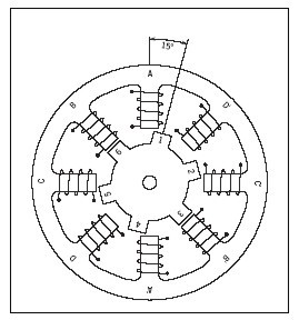
the easiest to understand from a structural point of view. Figure 1 shows a cross-section of a typical V.R. stepper motor. This type of motor consists of a soft iron multi-toothed
rotor and a wound stator. When the stator windings are energized with DC current the poles become magnetized. The rotation occurs when the rotor teeth are attracted to the energized stator
poles.
2. Permanent Magnet (PM)
Often referred to as a “tin can” or “stock” motor the permanent magnet step motor is a low-cost and low-resolution type motor with typical step angles of 7.5°to 15°. (48 – 24 steps/revolution) PM motors as the name implies have permanent magnets added to the motor structure
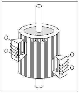
The rotor no longer has teeth as with the VR motor. Instead, the rotor is magnetized with alternating north and south poles situated in a straight line parallel to the rotor shaft. These magnetized rotor poles provide an increased magnetic flux intensity and because of this the PM motor exhibits improved torque characteristics when compared with the VR type.
3. Hybrid (HB).
The hybrid stepper motor is more expensive than the PM stepper motor but provides better performance with respect to step resolution, torque, and speed. Typical step angles for the HB stepper motor range from 3.6° to 0.9° (100 – 400 steps per revolution). The hybrid stepper motor combines the best features of both the PM and VR-type stepper motors. The rotor is multi-toothed like the VR motor and contains an axially magnetized con-centric magnet around its shaft. The teeth on the rotor provide an even better path which helps guide the magnetic flux to preferred locations in the airgap. This further increases the detent, holding, and dynamic torque characteristics of the motor when compared with both the VR and PM types.
Stepper Motor Advantages and Disadvantages Advantages
1. The rotation angle of the motor is proportional to the input pulse.
2. The motor has full torque at standstill (if the windings are energized)
3. Precise positioning and repeatability of movement since good stepper motors have an accuracy of 3 – 5% of a step and this error is noncumulative from one step to the next.
4. Excellent response to starting/ stopping/reversing.
5. Very reliable since there are no contact brushes in the motor. Therefore the life of the motor is simply dependent on the life of the bearing.
6. The motors response to digital input pulses provides open-loop control, making the motor simpler
and less costly to control.
7. It is possible to achieve very low-speed synchronous rotation with a load that is directly coupled to the shaft.
8. A wide range of rotational speeds can be realized as the speed is proportional to the frequency of the input pulses.
Size and Power
In addition to being classified by their step angle stepper motors are also classified according to frame sizes which correspond to the diameter of the body of the motor. For instance, a size 11 stepper motor has a body diameter of approximately 1.1 inches. Likewise, a size 23 stepper motor has a body diameter of 2.3 inches (58 mm), etc. The body length may, however, vary from motor to motor within the same frame size classification. As a general rule, the available torque out- put from a motor of a particular frame size will increase with increased body length.
Power levels for IC-driven stepper motors typically range from below watts for very small motors up to 10 – 20 watts for larger motors. The maximum power dissipation level or thermal limits of the motor are seldom clearly stated in the motor manufacturers’ data. To determine this we must apply the relationship P␣ =V×␣I.
For example, a size 23-step motor may be rated at 6V and 1A per phase. Therefore, with two phases energized the motor has a rated power dissipation of 12 watts. It is normal practice to rate a stepper motor at the power dissipation level where the motor case rises 65°C above the ambient in still air. Therefore, if the motor can be mounted to a heatsink it is often possible to increase the allowable power dissipation level. This is important as the motor is designed to be and should be used at its maximum power dissipation, to be efficient from a size/output power/cost point of view.
The Rotating Magnetic Field
When a phase winding of a stepper motor is energized with current a magnetic flux is developed in the stator. The direction of this flux is determined by the “Right Hand Rule” which states:
“If the coil is grasped in the right hand with the fingers pointing in the direction of the current in the winding (the thumb is extended at a 90° angle to the fingers), then the thumb will point in the direction of the magnetic field.” The magnetic flux path developed when phase B is energized with the winding current in the direction shown.
The rotor then aligns itself so that the flux opposition is minimized. In this case, the motor would rotate clockwise so that its south pole aligns with the north pole of the stator B at position 2 and its north pole aligns with the south pole of stator B at position 6. To get the motor to rotate we can now see that we must provide a sequence of energizing the stator windings in such a fashion that provides a rotating magnetic flux field which the rotor follows due to magnetic attraction.
Hysteresis motors
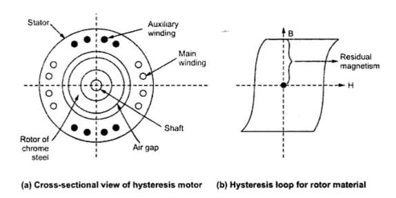
A distinctive feature of synchronous motors is that the speed is uniquely related to the supply frequency. As a result, several special types of synchronous motors have found wide applications in devices such as clocks, tape recorders, and photographs. One of the most extensively used is the hysteresis motor in which the rotor consists of a ring of a semi-permanent magnet material like high-carbon steel. At full speed, the motor operates as a permanent-magnet synchronous machine. If the speed is reduced by pulling the rotor out of synchronism, the stator field causes the rotor material to be cyclically magnetized around its hysteresis loop resulting in a rotor field that lags the stator field by a few degrees and continues to produce torque. These motors provide good starting torque with very low ripple and are very quiet. Their efficiency is low, and applications are restricted to small power ratings.
Construction:
It consists of:
(i) Stator:
A stator designed to produce a synchronously-revolving field from a single-phase supply. The stator carries main and auxiliary windings (which is called split phase hysteresis motor) so as to produce a rotating magnetic field. The stator can also be a shaded pole type (which is called a shaded pole hysteresis motor).
(ii) Rotor:
The rotor of hysteresis motors is made with magnetic material of high hysteresis losses. i.e. whose hysteresis loop area is very large. The rotor does not carry any winding or teeth.
Working Principle
When the stator is energized, it produces a rotating magnetic field. The main and auxiliary, windings must be supplied continuously at the start as well as in running conditions so as to maintain the rotating magnetic field. The rotor, initially, starts to rotate due to eddy-current torque and hysteresis torque developed on the rotor. Once the speed is near the synchronous, the stator pulls the rotor into synchronism.
In such cases, as relative motion between the stator field and rotor field vanishes, so the torque due to eddy-currents vanishes. When the rotor is rotating at a synchronous speed, the stator revolving field flux produces poles on the rotor. Due to the hysteresis effect, the rotor pole axis lags behind the axis of the rotating magnetic field. Due to this, rotor poles get attracted toward the moving stator poles. Thus rotor gets subjected to torque called hysteresis torque.
This torque is constant at all speeds. When the stator field moved forward, due to high residual magnetism (i.e. retentivity) the rotor pole strength remains maintained. So higher the retentivity, the higher is the hysteresis torque. The hysteresis torque is independent of the rotor speed. The high retentivity ensures continuous magnetic locking between the stator and rotor. Due to the principle of magnetic locking, the motor either rotates at synchronous speed or does not at all. Only hysteresis torque is present which keeps the rotor running at synchronous speed.
Hysteresis Motor advantages and disadvantages:
The advantages of hysteresis motor are:
1. As the rotor has no teeth, and no winding, there are no mechanical vibrations.
2. Due to the absence of vibrations, the operation is quiet and noiseless.
3. Suitability to accelerate inertia loads.
4. Possibility of multispeed operation by employing gear train.
The disadvantages of hysteresis motor are:
1. The output is about one-quarter that of an induction motor of the same dimension.
2. Low efficiency
3. Low power factor
4. Low torque
5. Available in very small sizes
ü Applications
Due to its noiseless operation, it is used in sound-recording instruments, sound-producing equipment, high quality record players, electric clocks, teleprinters, timing devices, etc.
Related topic – click here
- DC Machines – Types Of DC Motor | DC Motor Presentations
- Transducer Classification Of Transducers | Thermistors Application Of Thermistors
- Digital Electronics | Advantages And Disadvantages Of Digital Electronic | Digital Circuit
- What Are Semiconductor Devices? | Definition, Type, Conductor | Difference Between Semiconductors And Conductors Semiconductors
- Vector Groups Of Transformer | Application Of Transformer According To Vector Group
- DC GENERATOR | Principle, Types, & Applications
- ELECTRICITY POWER GENERATING STATION | Power Plants, Thermal Station & Hydroelectric Power Station
- RESONANT CIRCUITS | What Is Resonance?, Q-Factor
- DC Motors | Principles Of Operation Of DC Motor, Advantages Of DC Mo

