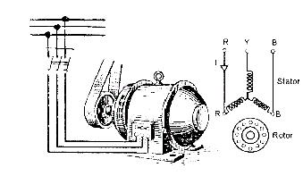
Three-Phase induction motor starting methods
The Various Methods of Starting of Induction Motor
• Direct-on-line starter
• Primary resistor or reactor starter
• Star delta starter
• Auto transformer starter
• Rotor resistance starter
Direct-on-line starter
• The starter is also called a line-to-line starter.
• The line starting is usually accomplished by means of a magnetic switch or contactor, which can be controlled by pushing buttons at convenient points.
• The “start” push button is normally open and the stops button is usually closed.
• When the start push button is pressed it closes a control circuit from the live line L, through the stop button the solenoid M of the magnetic contactor, and a temperature overload relay R, to the live line wire L2.
• The current ion the solenoid, M closes the main contactors and throws full line voltage on the motor.
• The motor starts running. It also closes the switch S, so that current is maintained in the control circuit through the stop push button, even after the start push button is released.
• The motor can be controlled from several points by using several push-button stations.
• The start push buttons are connected in parallel and the stop push buttons are in series.
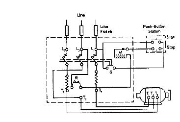
• The thermal overload relay is set to protect the motor against continuous overload. It is not affected by a large starting current, or by sudden momentary overloads.
• Fuses or circuit breakers in the supply line must carry the starting current.
• When the stop button is pressed; it disconnects the solenoid, M that de-magnetizes.
• The supply contractors go to the original position disconnecting the motor from the three-phase supply. The motor comes to stop. The start button has to be pressed to re-starting the motor.
Merits of DOL starter (direct on – line stator)
1. Simple in construction
2. Easy to install
3. Easy to maintain
4. Less expenditure on maintenance
Demerits of DOL starter ((Direct On – Line Stator)
1. Used only for small horsepower motors.
2. starting current is heavy since started with full voltage.
3. Suitable only for motors that attain their rated speed in a very short time.
Primary resistor starter
• The purpose is to drop some voltage and hence reduce the voltage applied across the motor terminals.
• The initial current drawn by the motor is reduced.
• The current varies directly from the voltage.
• But the torque varies as the square of the applied voltage.
• If the voltage applied across the motor terminal is reduced by 50%, starting current is reduced by 50 % but torque is reduced to 25% of the full-voltage value.
• The figure shows such a circuit, in which either resistance or reactance coils may be used to produce a sufficient reduction in stator voltage at the instant of starting.
• This method of starting is sometimes called “primary impedance acceleration”.
• Reduced voltage starting by means of series stator resistance will improve the starting power factor, but greater losses are produced.
• The advantage of reactor starting is reduced losses.
Star-delta starter
• This method is used in the case of motors that are built to run normally with a delta-connected stator winding.
Induction Motors: Analysis and Torque Control (Power Systems)
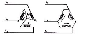
• By means of a triple-pole double-throw switch, the winding is connected in the star at starting and the delta connected when running as shown in the figure.
• When start connected, the voltage applied per phase is reduced by 3 times.
• The current taken from the line is 58 percent of that at normal voltage.
• But the starting torque is reduced to 0.582 or 33% of that at normal voltage.
• When the motor reaches sufficient speed the switch is thrown over thereby connecting the motor in delta across the line.
• It is clear that the star-delta switch is equivalent to an auto-transformer of ratio 1/3 or 58% approx.
• This method is cheap and effectively provides the starting torque required in not more than 1.5 times the full load torque.
• When the operating handle is put downwards the terminals A1, B1, and C1 are shorted. Now the stator windings are connected in star and energized by a three-phase supply.
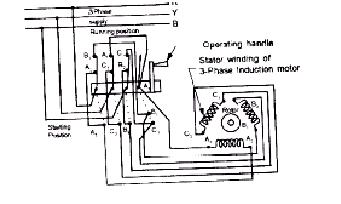
• When the motor has picked up the required speed the operating handle is put upwards and the stator windings are connected in delta across the three-phase supply.
The Induction Motor: Its Theory and Design, Set Forth by a Practical Method of Calculation
• In a star-delta starter also the no-volt release and overload release are provided to protect the motor against the failure of supply and overload.
• This type of starter is used to start the motors from the range of 7.5 hp to 20 hp squirrel cage induction motors.
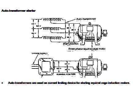
• The figure shows the usual connection made through an auto-transformer to a three-phase motor.
• By use of the control gear mounted on the top of the auto-transformer voltage applied to the motor is varied and finally full voltage is applied across the motor terminals.
• In the above method of starting there are no tapings in the auto-transformer. But in auto-transformer there are tapings.
• Only one tapping is used at the time of starting. The figure shows an auto-transformer with protective devices.
• The starter is also provided with change over switch. As the motor comes to full speed the change-over switch is thrown to the run position.
• The changeover switch may be hand-operated or automatic through a time delay relay
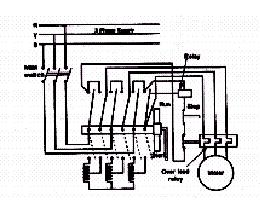
• This figure shows an autotransformer starter, which is provided with no-volt release and over-load release as protective devices.
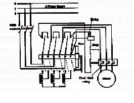
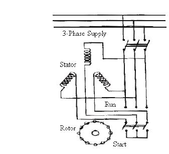
Rotor resistance starter
• Slip ring induction motors are practically always started with full line voltage applied across the stator terminals.
Induction Motors: Analysis and Torque Control (Power Systems)
• The value of starting current can be adjusted by introducing a variable resistance in the rotor circuit through slip rings
• The external resistance connected in the rotor circuit is in the form of a rheostat connected to a star.
• The resistance gradually cut out of the rotor circuit as the motor picks up speed and finally the slip rings are short-circuited.
• By increasing the rotor resistance, the rotor current is reduced at starting since impedance increases.
• The protective devices, no-volt relay, and over-load relay can be provided in this starter also.
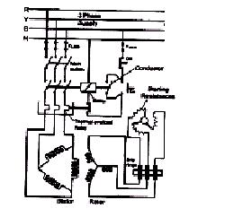
The figure shows a rotor resistance starter with protective devices.
• When the on button is pressed the no-volt relay energizes and closes the line contactor.
• The full voltage is applied to the stator terminals.
• When the on button is released, the relay gets supplied through the contactor.
• The rotor external resistance is cut step by step. Finally, the slip rings are short-circuited.
• The brushes may be lifted from slip-rings surfaces when the motor runs at normal speed or during normal working conditions.
• This is to avoid wear and tear and also to reduce frictional losses.
Related Topic – click here
- Dynamometer Type Three-Phase Wattmeter
- Three Methods Of Compounding In Steam Turbines
- Classification Of Moving Iron Instruments
- CONSTRUCTION OF D.C. MACHINE
- Three-Point Starter Measuring Instruments
- Electrodynamometer (Electrodynamics) Type Instruments
- STATIC & DYNAMIC CHARACTERISTICS OF ELECTRICAL MEASUREMENT SYSTEM
- Starting Of Induction Motor | Types Of Three-Phase Induction Motor Starting Methods
- Electrical Engineering History Facts Words | History Of E

