Single phase transformer
The basic theory of a transformer is not difficult to understand. To simplify matters as much as possible, let us first consider an ideal transformer, that is, one in which the resistance of the winding is negligible and the core has no losses.

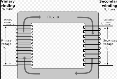
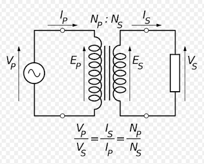
This is a single-phase transformer having two winds the primary winding and the secondary winding.
follow in the primary winding. Since the primary resistance is negligible and there are no losses in the core, the effective resistance is zero and the circuit is purely reactive.
Hence the current wave Im lags the impressed voltage wave. The reactance of the circuit is very high and the magnetizing current is very small. This current in the N1 turns of the primary magnetizes the core and produces a flux ø that is at all times proportional to the current if the permeability of the circuit is assumed to be constant, and therefore in time phase with the current.
The flux, by its rate of change, includes in the primary winding E1 which at every instant of times is equal in value and opposite in direction to V1. It is called the current e.m.f of the primary.
The value that the primary current attains must be such that the flux that it produces in the core is of sufficient value to induce in the primary the required counter e.m.f. electro-motive force.
Since the flux also threads or links the secondary winding a voltage E2 is induced in the secondary, this voltage is likewise proportional to the rate of change of flux and so is in the time phase with E1, but it may have any value depending upon the number of turns N2 in the secondary.
Working principle
A single-phase transformer is an electrical device that uses electromagnetic induction to transfer electrical energy between two or more circuits. It works on the principle that when a varying current flows through a primary coil, it induces an electromotive force (EMF) in a secondary coil that is wound around the same core. This EMF causes a current to flow in the secondary circuit, resulting in the transfer of energy from the primary circuit to the secondary circuit.
Application of single-phase transformers
Single-phase transformers are used in a wide range of applications, including:
- Power distribution: Single-phase transformers are commonly used in power distribution systems to step down the high-voltage power from the utility grid to a lower voltage that is safe for use in homes and businesses.
- Industrial equipment: Single-phase transformers are used to power industrial equipment such as motors, welding machines, and other types of machinery.
- Electronics and appliances: Single-phase transformers are used to power electronic devices and appliances, such as televisions, computers, and air conditioners.
- Medical equipment: Single-phase transformers are used in medical equipment such as MRI machines, X-ray machines, and other diagnostic equipment.
- Lighting: Single-phase transformers are used to power lighting systems in homes, businesses, and industrial settings.
- Battery charging: Single-phase transformers are used in battery charging systems for automobiles, boats, and other vehicles.
- Signaling systems: Single-phase transformers are used in signaling systems like telephones, intercoms, and alarms.
- Power factor correction: Single-phase transformers are used to improve power factor in AC power systems.
Overall singal phase transformers are very versatile and can be used in a wide range of applications that require the transfer of electrical energy between circuits.
E.M.F equation of a transformer
Let,

N1 = Number of turns in the primary winding
N2 = number of turns in the secondary winding
øm= maximum flux in the core,
wb
= Bm. A, – where Bm is the maximum flux density in the core and A is the core area,
f = frequency of a.c. input Hz.
E. M.F equation

Transformer on no load

A transformer is said to be on no-load if its secondary side is open and the primary is connected to a sinusoidal alternating voltage V1. The alternating applied voltage will cause the flow of alternating current in the primary winding which will create alternating flux. This primary input current Io is under no-load condition supply.
- Iron losses in the core (for example. Hysteresis loss and eddy current loss.)
- A very small amount of copper loss in the primary (there being no copper loss in the secondary as it is open).
Transformer on load

The transformer is said to be loaded when the secondary circuit of a transformer is complete through an impedance or load. The magnitude and phase of secondary current I2 with respect to secondary terminal voltage will depend upon the character of load, i.e, current I2 will be in phase, lag behind and lead the terminal voltage V2 respectively when the load is purely respective, inductive, and capacitive.
The secondary current I2 sets up its own ampere-turns and creates its own flux opposing the main flux. The opposing secondary flux weakens the primary flux momentarily and hence causes more current to flow in the primary.
- Whatever the load condition, the net flux passing through the core is approximately the same as at no-load.
- Since the core flux remains constant at all loads, the core loss almost remains constant under different loading conditions.
Related topic – click here
- DC Machines – Types Of DC Motor | DC Motor Presentations
- Transducer Classification Of Transducers | Thermistors Application Of Thermistors
- Digital Electronics | Advantages And Disadvantages Of Digital Electronic | Digital Circuit
- What Are Semiconductor Devices? | Definition, Type, Conductor | Difference Between Semiconductors And Conductors Semiconductors
- Vector Groups Of Transformer | Application Of Transformer According To Vector Group
- DC GENERATOR | Principle, Types, & Applications
- ELECTRICITY POWER GENERATING STATION | Power Plants, Thermal Station & Hydroelectric Power Station
- RESONANT CIRCUITS | What Is Resonance?, Q-Factor
- DC Motors | Principles Of Operation Of DC Motor, Advantages Of DC Motors


