data communication in 8081
• The fastest way of transmitting data, within a microcomputer is parallel data transfer.
• For transferring data over long distances, however, parallel data transmission requires too many wires.
• For long-distance transmission, data is usually converted from parallel form to serial form so that it can be sent on a single wire or pair of wires.
• Serial data received from a distant source is converted to parallel form and it can be easily transferred on microcomputer buses.
• The types of communication systems are,
1. Simplex 2. Half-duplex 3. Full-duplex
- In simple communication, data can be transmitted only in one direction, ie. data from sensors to processors. Eg: commercial radio stations.
- In half-duplex transmission, data can be transmitted in either direction between two systems but can occur only in one direction at a time. Eg: a two-way radio system, where one user always listens while the other talks because the receiver circuitry is turned off during transmission.
- In a full duplex, the data can be sent and received at the same time. Eg: A normal phone conversation.
· Serial data can be sent in two ways.
They are,
1. Synchronous communication
2. 2. Asynchronous communication
In synchronous transmission, data are transmitted in blocks at a constant rate.
The start and end of a block are identified with specific bytes or bit patterns.
In asynchronous transmission, data is transmitted one by one.
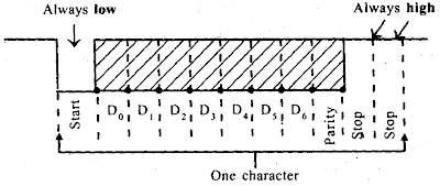
The beginning of a data character is indicated by the line going low for a 1-bit time. This bit is called a start bit.
The data bits are then sent out on the line one after the other. Note that the least-significant bit is sent out first. Depending on the system, the data word may consist of 5, 6, 7, or 8 bits.
Following the data, bits is a parity bit, which is used to check for errors in received data.
The line is returned high for at least 1-bit time to identify the end of the character. This always-high bit is referred to as a stop bit. Some systems may use 2 stop bits.
The bit format for asynchronous data transmission is,
• The term baud rate is used to indicate the rate at which serial data is being transferred.
Baud rate = 1/ time for a bit cell
• A device such as INTEL 8251A, which can be programmed to do either asynchronous or synchronous communication, is often called USART (Universal Synchronous Asynchronous Receiver Transmitter).
• A device such as the National 1NS8250, which can only do asynchronous communication, is often referred to as a Universal Asynchronous Receiver Transmitter (UART).
• For sending serial data over long distances the standard telephone system is a convenient path because the wiring and connections are already in place.
• Standard phone lines are often referred to as switched lines because any two points can be connected together through a series of switches and have a bandwidth of about 300 to 3000 Hz.
• But digital signals require a very large bandwidth (typically 5 MHz). Therefore, digital signals cannot be sent directly over standard phone lines. So, the digital signals are converted to audio-frequency tones, which are in the frequency range.
• The device used to do this conversion and to convert transmitted tones back to digital information is called a MODEM.
• Modems and other equipment used to send serial data over long distances are known as data communication equipment or DCE. The terminals and computers that are sending or receiving the serial data are referred to as data terminal equipment or DTE.
RS-232C serial data standard:
• In serial I/O, data can be transmitted as either current or voltage.
• When data are transmitted as voltage, the commonly used standard is known as RS-232C.
• This standard, proposes a maximum of 25 signals for the bus used for serial data transfer.
• The 25 signals of RS-232C are,
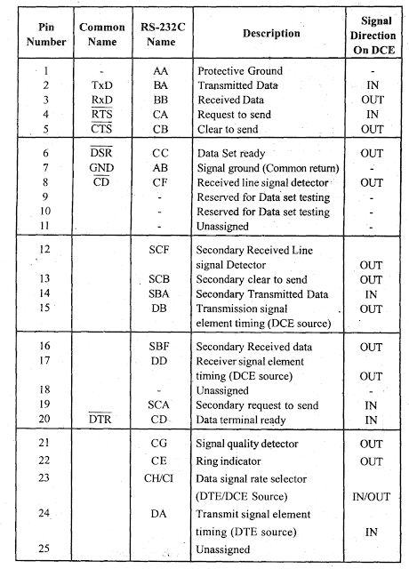
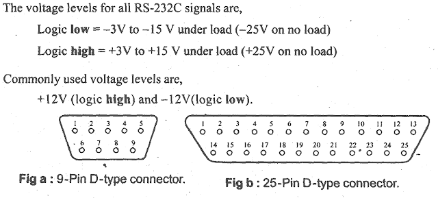
• In practice the first 9-signals are sufficient for most of the serial data transmission scheme and so the RS-232C bus signals are terminated on a D-type 9-pin connector.
• When all the 25 signals are used, the RS-232C serial bus is terminated on a 25-pin connector.
• The RS-232C signal levels are not compatible with TTL logic levels. Hence for interfacing TTL devices, level converters or RS-232C line drivers are employed.
• The popularly used level converters are,
1. MC1488 – TTL to RS-232C level converter.
2. MC1489 – RS-232C to TTL level converter.
3. MAX 232 – Bidirectional level converter.
(Max 232 is equivalent to a combination of MC 1488 and MCI 489 in a single IC)
• The pin diagram of MAX 232 is,
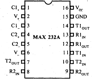
• For MAX 232 all capacitors should be 1µF.
• The voltage rating of all capacitors should above 10V.


