INTRODUCTION:
Resonance is the name given to a phenomenon when an object shows the maximum response when it is subjected to a certain frequency known as the ‘resonant frequency’ or ‘natural frequency’ of that object. Resonance can be both mechanical and electrical. Mechanical resonance can be observed in any vibrating body such as a tuning fork. However, resonance in electrical circuits is observed in RLC circuits.
RESONANCE IN RLC CIRCUITS:
The resonant circuit is a combination of R, L, and C elements having a frequency response characteristic similar to the one appearing in a given figure.
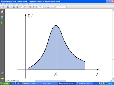
Note in the figure that the response is a maximum for the frequency fr, decreasing to the right and left of this frequency. In other words, for a particular range of frequencies, the response will be near or equal to the maximum.
CONDITION FOR RESONANCE:
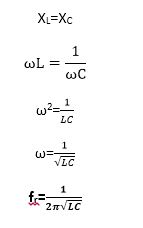
The required condition for resonance is that circuit’s capacitive reactance becomes equal to its inductive reactance.
XL=XC
TYPES OF RESONANCE:
There are two types of resonance based on how the inductor and capacitor are connected in the circuit:
I. Series Resonance
II. Parallel Resonance
Series Resonance
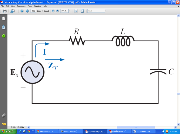

Resonance in series circuits occurs when the total reactance of the circuit becomes zero i.e. inductive and capacitive reactance have equal values and they cancel each other as they have a phase difference of 180⁰.
MINIMUM IMPEDANCE:
Since circuit elements are in series total impedance is given by:
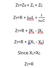
This is the minimum impedance of the resonant circuit.
The phasor relationship of total impedance is given by the phasor diagram given below.
MAXIMUM CURRENT:
At the resonant frequency, the RLC circuit shows the maximum response of current.
Using Ohm’s law:

This show that current is inversely proportional to the impedance of the circuit. In the resonance, state impedance is minimum so the current would be maximum.
RESONANT FREQUENCY:
The resonant frequency can be determined in terms of inductance and capacitance by examining the defining equation for resonance.
UNIT POWER FACTOR:
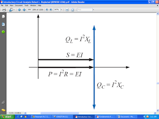
The average power to the resistor at resonance is equal to I2R, and the reactive power to the capacitor and inductor are I2XC and I2XL respectively. The power triangle shows that the total apparent power of the circuit is equal to the power dissipated due to the resistor.
Power triangle for the series resonant circuit at resonance.
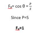
The power factor for the circuit at resonance is:
PARALLEL RESONANCE:
Resonance in parallel circuits occurs when the parallel impedance is maximum. The current is in phase with the voltage during parallel resonance.
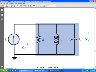
The circuit resonates at a frequency that makes the inductive reactance XL and the capacitive reactance XC equal, so the two branch currents i.e. through the inductor and through the capacitor are equal but opposite in direction. Hence they cancel out the effect of each other and as a result, the net current drawn from the source is zero. In actual practice, the current is not exactly zero but has a minimum value due to the small resistance of the coil.
MAXIMUM IMPEDANCE:
Since the circuit is in parallel its admittance is given by:
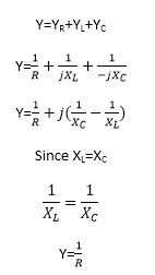
This shows that in parallel resonance circuits, minimum admittance is observed. So impedance is maximum.
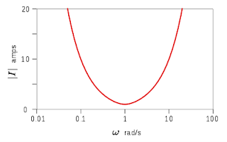
MINIMUM CURRENT:
At resonant frequency parallel RLC circuit shows minimum current.
Using Ohm’s law:

This show that current is inversely proportional to the impedance of the circuit. In parallel circuits, IMPEDANCE is maximum so the current would be minimum at the resonance state.
RESONANT FREQUENCY:
In parallel circuits, the resonant frequency is the same as in series circuits i.e.

EXPLANATION OF RESONANCE PHENOMENON IN PARALLEL CIRCUITS:
At resonance, the branch currents IC and IL each may be larger than the source current. The reason is that the current impedance is high, the overall current is zero but the voltage developed across the parallel circuit is high. The individual currents developed in the inductance IL and capacitance IC at resonance can be very large but are out of phase with each other resulting in a very low combined current.

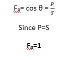
UNIT POWER FACTOR:
The average power to the resistor at resonance is equal to I2R, and the reactive power to the capacitor and inductor are I2XC and I2XL respectively. The power triangle shows that the total apparent power of the circuit is equal to the power dissipated due to the resistor.

Power triangle for the parallel resonant circuit at resonance
The power factor for circuit at resonance is:
Also read,

