
Relay Setting of IDMT and Instantaneous over current and earth fault Relay
Relay is a protecting device that detects any kind of abnormal happenings(fault) in the power system or in power system elements (like a transformer, generator, etc.) and sends a signal to the circuit breaker to isolate the fault or to the alarm, the circuit to raise an alarm.
RELAY IDENTIFICATION:
51- Over the current IDMT relay
51N-IDMT earth fault relay
50-Over current definite time relay
50N-Definite time earth fault relay
49-Thermal overload relay
46-Negative sequence relay
48-Motor starting supervision
66-Restart inhibit for motor
27-Under voltage relay
87-Differential relay
IDMT stands for Inverse Definite Minimum Time relay
SETTING METHODS:
51 & 51N
51 and 51N are both inverse time relays and are used to detect phase fault and earth fault respectively. Their setting methods are the same but the only difference is that the pick-up of 51 is higher than that of 51N.
Please check our article CT connection to sense Earth fault/Earth Faults Detection Philosophy to know Earth fault has been detected.
The following parameters are required to calculate the settings of 51 and 51N.
a. PICK-UP: this is the value of current through the relay for which the relay picks up.
b. PSM (Plug Setting Multiplier): this is the ratio of fault current through the relay coil and pick-up current. (it is relays inherent property)
c. TSM (Time Setting Multiplier): it is the ratio of the required relay operating time and actual relay operating time.
Basically, if the TSM=1 then the relay operating time is very high, that’s why a fraction is given as TSM to decrease the relay operating time as per requirement or to coordinate with the up and downstream feeders.
Sample calculation:
Pick-Up Calculation:
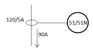
The single diagram shows a very simple and typical line, through which 90A current is flowing, and a CT of rating 120/5A is connected via which the 51 and 51N relays are connected.
Let’s say, that relay 51 will pick up for 120% of the full load current.
So current seen by the relay will be,
=120% X FLC X CT Sec. /CT primary
=1.2 X 90 X 5/120
=4.5 A
So pick-up setting or pick-up current of the relay is 4.5 Amp.
Now, remember one thing, some relay manufacturers make their relay pick-up range in the following manner, say 0.5-10 X CT sec. That means the CT secondary will be multiplied within the relay program. So here multiplication with CT secondary will not be applicable.
For this type of relay, the pick-up will be
=1.2 X 90/120=0.9
The relay will display the following setting- 0.9 X CT sec (In) (In general In is referred to as the relay-rated current, which is, in general, the same as the CT secondary current. That is CT secondary and relay-rated current shall be the same. However, there is an exception for earth fault relay, which is beyond the scope of this article)
So, it is strictly required to read the relay catalog and know the setting range.
The method of calculating pick up of 51N is the same as mentioned above, but the pick-up is considered as 5-10% of full load current, if the feeder is being fed from a transformer that has NGR then pick-up may be considered as 5-10% of NGR rating.
Suppose a transformer has an NGR of 400A for 10 sec i.e. limiting earth fault current up to 400 A with NCT having a ratio of 200/1A.
Then pick-up will be set as
=10% X 400 X CT sec/CT prim.
Here also see the relay catalog to know if the CT sec is required to be multiplied or if it will be multiplied internally.
Following the above-mentioned process pick up of inverse time over current and earth fault relay is calculated.
However, for earth fault protection is better to select the minimum available pick-up to ensure maximum sensitivity.
PSM calculation:
PSM = Fault current in relay coil/pick up current through the relay coil.
= (Fault Current X CT secondary/CT primary)/ Pick up current through the relay coil.
Suppose the fault current is 1000A.
So, PSM will be
= ((1000X5)/120)/4.5
=41.66/4.5
=9.26
There are several types of IDMT relay characteristics available now, and according to the characteristics, the relay operating time is determined. The formulas are as follows:
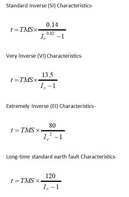
Ir the PSM value which has been calculated earlier.
Now,
Suppose we have to operate the relay at 0.75 sec (say).
So, TMS will be (for standard inverse curve)= 0.75X((9.260^0.02)-1)/0.14
=0.24
So settings are –
1. Pick up= 4.5 or 0.9 X In(it will be according to the relay)
2. TMS=0.24
Some typical settings-
PHASE FAULT
1. B/C AND I/C OF MCC: 80% OF THE BUSBAR RATING OR 120% OF THE CONNECTED LOAD (TAKE THE AVAILABLE DATA).
2. UPSTREAM RELAY OF SL NO. 1 ( i.e. O/G OF PCC): SELECT PICK UP HIGHER THAN SELECTED FOR SL NO. 1
3. B/C AND I/C OF PCC: 120% OF TRANSFORMER FULL LOAD CURRENT.
4. AT THE H.V SIDE OF THE TRANSFORMER (51 which is back up of the downstream or LV side 51 relays): 130% OF TRANSFORMER HV SIDE FULL LOAD CURRENT.
GROUND FAULT
1. B/C AND I/ OF MCC: 15-30% OF BUSBAR RATING.
2. UPSTREAM RELAY (O/G OF PCC):30% OF BUS BAR RATING
3. B/C AND I/C OF PCC: 20% OF TRANSFORMER FULL LOAD CURRENT.
For 51N always use the minimum available settings, which will ensure a maximum percentage of protection.
TIME GAP
TRY TO MAINTAIN A TIME GAP OF 0.25 SEC BETWEEN RELAYS.
50 & 50N
These can be used as definite time relays or instantaneous relays.
For relay 50 connected at the H.V. side of the transformer: For such connection, the pickup shall be more than the inrush current of the transformer. Otherwise, the relay will trip during the transformer’s starting.
Inrush current is generally 10-15 times transformer FLC.
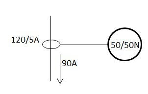
Say transformer H.T FLC is 90 A.
Then inrush will be 10×90=900 A. we set the pick up of the relay as 910 A.
So setting is=910×5/120=37.9 A or (910/120) X In=7.58 X In as per the available Relay functions.
Here also consider the relay catalog as mentioned earlier.
If the 50 relays are connected to the motor feeder for motor protection then pickup will be higher than the starting current of the motor.
The time delay may or may not be given depending upon the requirement of instantaneous or time-delayed operation.
The 50N setting method is also the same but uses a minimum pick-up setting, generally, 5-10% of the NGR rating can be used. If NGR is not there then the same % of FLC can be used, but try to use a minimum pick-up setting for the relay to ensure a maximum percentage of protection.
IDMT (Inverse Definite Minimum Time) Relay Calculation
Overcurrent and Earth Fault Relay Setting
Setting calculation is separated for overcurrent and earth fault relay. For both settings, there are few input parameters:
- Name of Feeder
- Load Current: (IL) in Amps
- Min Fault Current (Line-Line) in Amps
- Max Fault Current (Line-Line) in Amps
- Relay Type
- Relay Code
- Relay No
- CT Primary Current (in Amps)
- CT Secondary Current (in Amps)
- Relay Error (%)
- CT Error (%)
- Overshoot (in seconds)
- C.B Interrupting Time (in seconds)
- Safety (in seconds)
Summary of overcurrent and earth fault relay settings:
- Actual Plug (Relay Pick up) setting
- Plug Setting Multiplier (PSM)
- Time setting
- Total Grading Time
- Low Over Current Setting: (I>)
- Actual Operating Time of Relay (tI>)
- High Over Current Setting: (I>>)
- Actual Operating Time of Relay (tI>>)


