
• It is a device to transfer the data directly between the I/O device and memory without through
the CPU. So it performs a high-speed data transfer between the memory and the I/O device.
• The features of 8257 is,
1. The 8257 has four channels and so it can be used to provide DMA to four I/O
devices
2. Each channel can be independently programmable to transfer up to 64kb of data
by DMA.
3. Each channel can independently perform read transfer, write transfer, and verify the transfer.
• It is a 40-pin IC and the pin diagram is,

Functional Block Diagram of 8257:
• The functional block diagram of 8257 is shown in fig.
• The functional blocks of 8257 are data bus buffer, read/write logic, control logic, priority resolver, and four numbers of DMA channels.
• Each channel has two programmable 16-bit registers named as address register and count register.

• Address register is used to store the starting address of the memory location for DMA data transfer.
• The address in the address register is automatically incremented after every read/write/verify the transfer.
• The count register is used to count the number of bytes or word transferred by DMA
• The format of the count register is,

• 14-bit B0-B13 is used to count value and 2-bits is used to indicate the type of DMA
transfer (Read/Write/Veri1 transfer).
• In reading transfer the data is transferred from the memory to the I/O device.
• In write transfer the data is transferred from the I/O device to memory.
• Verification operations generate the DMA addresses without generating the DMA
memory and I/O control signals.
• The 8257 has two eight-bit registers called mode set register and status register.
• The format of the mode set register is,

• The use of mode set register is,
1. Enable/disable a channel.
2. Fixed/rotating priority
3. Stop DMA on the terminal count.
4. Extended/normal write time.
5. Auto reloading of channel-2.
• The bits B0, B1, B2, and B3 of the mode set register are used to enable/disable channels -0, 1, 2
and 3 respectively. A one in these bit positions will enable a particular channel and a zero
will disable it
• If the bit B4 is set to one, then the channels will have rotating priority, and if it zeroes then the channels wilt have fixed priority.
- In rotating priority after servicing a channel its priority is made as lowest.
- In fixed priority, channel-0 has the highest priority and channel-2 has the lowest priority.
• If the bit B5 is set to one, then the timing of low write signals (MEMW and IOW) will be extended.
• If the bit B6 is set to one then the DMA operation is stopped at the terminal count.
• The bit B7 is used to select the autoload feature for DMA channel-2.
• When bit B7 is set to one, then the content of channel-3 count and address registers are loaded in channel-2 count and address registers respectively whenever the channel-2
reaches the terminal count. When this mode is activated the number of channels available for
DMA reduces from four to three.
• The format of the status register of 8257 is shown in fig.
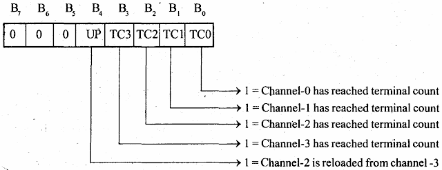
• The bit B0, B1, B2, and B3 of status register indicates the terminal count status of channel-0, 1,2 and 3 respectively. One in these bit positions indicates that the particular
the channel has reached the terminal count.
• These status bits are cleared after a read operation by the microprocessor.
• The bit B4 of the status register is called the update flag and one in this bit position indicates that the channel-2 register has been reloaded from channel-3 registers in the autoload mode of operation.
• The internal addresses of the registers of 8257 are listed in the table.


