Classification of pressure measuring instruments based on construction and working principles
Four basic types of pressure measuring instruments are;
1. Liquid column elements:
- Barometer
- Manometer –u tube, enlarged leg well-inclined leg
2. Elastic element gauge:
- Bourdon tube
- Bellows
- Diaphragm
- Capsule
3. Electrical transducers:
- Resistance and inductance type
4. Force–balanced devices:
- Deadweight gauge
- Ring gauge
- Bell gauge
BAROMETER:
The barometer is used to measure atmospheric pressure. Atmospheric pressure is the pressure exerted by the air surrounding the earth that goes on decreasing away from the earth’s surface.
Working principle:
Barometric liquid balances the atmospheric pressure against vacuum and pressure head reading is obtained in the absolute units.
Construction and working:
The barometer has a glass tube closed at one end and opened at the other; the length of the tube must be greater than 76.2 cm. the tube is first completely filled with mercury and the open end is temporarily plugged. Then the tube is inverted so that plugged end is immersed in a mercury pan. When the plug is removed, the mercury in the tube drops by a certain amount, creating a vacuum at the top of the tube, and then the reading ‘h’ is noted. The reading ‘h’ is proportional to atmospheric pressure acting on mercury in the pan. Note that this atmospheric pressure reading is in absolute units.
We have stated that vacuum is present at the top of the tube above mercury, but actually, there is the vapor pressure of mercury acting on mercury pressure ’P’ kg/cm2 is given by P= 6.66 X 10⁻³h
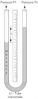
MANOMETER:
The device is used to know about the pressure difference in the pipeline, it is simple in construction, and the basic law of physics is applied for the calculation of the pressure drop. It is a glass or metal tube with a ‘U’ bend providing two legs. Manometric fluids such as mercury or carbon tetrachloride etc., where the density should be higher than the fluid which flows through the pipe, manometric fluid will be filled in the tube for the value, the two legs are connected to the points on which we are interested to calculate the differential pressure when this done the fluid which flows in the pipe or tube will enter into both the legs, the pressure on the leg will differ showing the deflection of height in the manometric fluid.
Principle: all manometers work on the effect of the hydrostatic pressure exerted by a liquid column. In a manometer, unknown pressure is determined by balancing it against some known pressure or vacuum.
Construction and working:
The U-tube manometer consists of a glass U-tube partially filled with a suitable liquid like water, mercury, etc. one of the arms or legs of the manometer, is connected to an unknown pressure tap to be measured while the other is connected to another pressure tap or it is left open to atmosphere.
When there is a difference in pressure between two arms of the manometer, liquid levels in the two arms of the manometer, and liquid levels in the two arms do not match. This level difference in the two arms of the manometer represents differential pressure (P1-P2). The static balance equation is
- P2-P1=h ρ g
h=height difference
ρ=mass density of manometer liquid
If the fluid over manometer liquid has appreciable density, then the static balance equation can be written as:
- P2-P1= h (ρm – ρl) g
h= height difference
ρm = mass density of manometric liquid
ρl = mass density of fluid over manometric liquid
INCLINED–LEG MANOMETER:
The construction is very similar to an enlarged leg manometer except that the small diameter tube is inclined to the vertical axis.
When pressure P1 and P2 are applied then liquid rises in the tube, and the level of manometric liquid inside the tube is measured from zero level along the inclined tube which represents the differential pressure (P1 – P2) the static balance equation can be written as
- P2-P1= ρd sinα[1+(A1/A2)]
α=anlge of inclination of the inclined leg
d= height difference measured
Advantages:
- Due to the inclined leg, the manometer reading gets amplified. Hence it can be used for the measurement of low pressures which cannot be measured by other manometers.
- By reducing angle α, the scale length and hence the sensitivity can be increased.
MANOMETRIC LIQUIDS:
Desirable properties of good manometric liquid should have
- Low-freezing point
- High boiling point
- Non-wetting characteristics
- Low surface tension
- Chemically inert
- Clear visible interface
- Ability to maintain density at various temperatures
MANOMETRIC FLUIDS USED IN PRACTICE ARE:
- Mercury: Mercury has a low freezing point(-38F) and high boiling point (675F) but it corrodes many metals and it is poisonous and expensive.
- Water with coloring agents: color agents reduce the surface tension of pure water, which reduces the capillarity effect in the manometer.
- Benzene, Kerosene, CCl4, toluene, etc. to make CCl4 visible a few iodine crystals can be added.
Calibration:
The manometer is subjected to the known differential pressure and the corresponding height difference is noted. The calibration curve can be prepared by plotting height difference versus differential pressure. This curve can be used to get the differential pressure for a certain height difference.
- Sources of error: Temperature effect: A rise in temperature causes a decrease in manometric liquid density that affects the calibration which leads to an error.
- Capillary rise: to avoid the capillary rise effect, the tube diameter should be over 10mm otherwise capillary rise results in an error in pressure reading.
- Meniscus shape: For water, the free surface is concave while the mercury-free surface is convex. The level of manometric liquid should be noted at the center of the meniscus.
Advantages and limitations:
Advantages:
- Simple inexpensive construction
- High accuracy and sensitivity
- Can be used for low-pressure measurements
- The desired span can be obtained just by using suitable manometric liquids
- The pressure range of manometers is 3 to 100KPa.
Limitations:
- No over-range protection
- Requires large space
- Non-portable
- Leveling is required
- Condensation of test liquid affects the reading.
ELASTIC PRESSURE TRANSDUCERS
Transducers are a device that converts one form of energy into some other form. These pressure gauges have an elastic element that converts pressure signals into proportional mechanical displacement. In this article, we study the Bourdon gauge, bellow gauge, diaphragm gauge, and capsule gauge.
BOURDON PRESSURE GAUGE:
Principle: E.Bourdon introduced the Bourdon tube in 1852 as a curved or twisted tube having a non-circular transverse section, according to Bourdon’s theory a tube having an internal cross-section that is not a perfect circle if bent or distorted has the property of changing its shape with internal pressure variation, this causes the free end deflection of the tube which can be taken as the measurement of change in pressures inside it.
Construction: Bourdon pressure gauges use different types of Bourdon springs as C-shaped Bourdon tubes which are formed by winding the tube to form a segment of a circle having an arc- length of about 270 degrees. Inspiral type, the number of turns is wound in the shape of a spiral about a common axis. In helix type number of turns is wound in helix form. In these figures, ‘P’ indicates the direction of application of pressure, while ‘T’ indicates tip travel for the rise in pressure
We study the C-shaped Bourdon tube gauge as it consists of a C-shaped Bourdon tube, tip, adjustable link, segments lever, sector, pinion, spring, and pointer. A C-shaped Bourdon tube is a thin-walled tube having a non-circular or nearly elliptical transverse section as one end of the tube is soldered or welded to a socket at the base through which pressure is fed inside the tube while the other end is sealed by a tip. Adjustable links, segment lever sector, or pinion are connected to the tip, which converts the linear motion of the tip into proportional rotary motion which is given to the pointer that moves on the scale calibrated in terms of pressure. A hairspring is connected to the spindle on which the sector is mounted, which provides the necessary tension for meshing the sector and pinion thus eliminating any backlash.
Under range, protection is particularly required for gauges having partial ranges (like 20 to 50psi).
Bourdon tube material: a bourdon spring can be made of any metal or alloy that exhibits satisfactory elastic properties. The material used is- brass, phosphor bronze, Monel, beryllium, copper, stainless steel, etc.
Pressure range:
| C-shaped tube | 0 to 1,00,000 psi |
| Gauge pressure | 0 to 12,000psig |
| Absolute pressure | 0 to 100 psi |
| Vacuum | 0 to 30’’ Hg |
Working:
When fluid under pressure to be measured enters the bourdon tube, its cross-section tries to become more and more circular which caused the straightening of the tube. Since one end of the tube is fixed straightening cause the free end to deflect which is called tip travel. The amount of tip travel for a given rise in pressure is a function of tube length wall thickness cross-section geometry and elastic module of the tube material. This linear tip travel is guided and amplified by an adjustable link and segment lever and then it is given to sector and pinion arrangement. Sector and pinion convert the amplified tip travel into proportional rotary motion of the pointer connected to the pinion. The pointer defection can be read on the scale calibrated in terms of pressure.
Helical and spiral types of bourdon tubes have many numbers of turns hence the top movements for giving change in pressure is more than that for single turn C- a shaped tube.
Gauge pressure measurement: when unknown pressure is fed inside the bourdon tube and its outside is exposed to the atmosphere, the reading would be in gauge units.
Absolute pressure measurement: when unknown pressure is fed inside the tube and its outside(instrument case)is evacuated, then the reading would be in absolute units.
Vacuum measurement: the procedure is similar to gauge pressure measurement. The Bourdon vacuum gauge has poor accuracy.
Calibration:
Bourdon gauge is calibrated using a dead weight tester or by comparison calibration.
Advantages, limitations, and Applications:
Advantages:
1. low cost and simple construction
2. wide pressure range
3. high accuracy in relation to low cost
Limitations:
1. Low spring gradient
2. Susceptibility to shock and vibration
3. Bordon tube material possesses some hysteresis in a pressure cycle, hysteresis can be kept minimum by proper heat treatment and by using proper materials.
Types of Pressure gauges
To measure absolute pressure, gauge pressure, vacuum or draft pressure, and differential pressure three physical methods can be used based on the working condition
- Using a liquid column where the density and height of liquid are important to measure pressure.
- Using pressure-sensing elements
- By electronic methods
Let’s see if pressure gauges of different types and pressure ranges can work.
Diaphragm Pressure Gauge:
This pressure gauge is widely used to measure the pressure of a reactor or closed container.
Principle:
When pressure is applied on either side of the tight diaphragm, by which it gets deflected. This deflection of the diaphragm is proportional to the differential pressure across it. Thus differential pressure across the diaphragm can be measured in terms of its deflection.
Construction and working:
Diaphragm gauge uses metallic or non-metallic diaphragms along with the pointer mechanism.
1) Metallic diaphragms: These elements are flexible circular discs, either flat or corrugated. These elements convert pressure signals to pointer deflection.
The metal is heat treated before forming a diaphragm to produce a maximum elastic limit. After forming, the diaphragms are heat treated to relieve internal stresses. A diaphragm is usually designed so that the deflections versus pressure characteristics are as linear as possible over a specified pressure range. Metals used are brass, beryllium copper, stainless steel, and phosphor-bronze.
2) Non-metallic diaphragms: very bendable diaphragms are used and so they can be utilized to measure vacuum and low pressures available. Non-metallic materials used are synthetic rubber, neoprene, leather, Teflon, nylon, or dacron.
Pressure range:
For non-metallic diaphragms 0 to a 10-inch water
Minimum= 0 to 2 inches of water
Maximum=0 to 400 psi
Advantages:
1. Small in size and cheaper
2. By using corrosion-resistant material it has a long life
3. We can obtain perfect linearity functions
Limitations:
1. Cannot be used for high pressure
2. Vibration will affect the reading
Thermocouple Types and Comparison
Thermocouple types and probes and thermocouple cables used for measurement of temperature, mode of furnace thermocouple working and high-temperature thermocouple working procedure, and the functioning of the thermistor. Calibration of temperature sensors, the material of construction of various thermocouples based on the utilization, mechanism of fitting the thermocouple to the process equipment, and working principle of thermocouple testing. B, E, J, K, R,S, T types of thermocouple comparison
| Sr no | Type | Positive wire | Negative wire | Temperature range 0C | Linearity |
| 1 | B | Pt-70—Rh-30 | Pt-94—Rh-6 | 0 to 1860 | Good at high temperature |
| 2 | E | Chrome | Constantan | -196 to 999 | Good |
| 3 | J | Iron | Constantan | -196 to 760 | Nearly linear between 149 to 438 |
| 4 | K | Chrome | Alumel | -190 to 1371 | Most linear |
| 5 | R | Pt-87—Rh-13 | Platinum | -18 to 1704 | Good at high temperature |
| 6 | S | Pt-90—Rh-10 | Platinum | -18 to 1760 | Good at high temperature |
| 7 | T | Copper | Constantan | -190 to 399 | Same as J |
| 8 | Tungsten W | W 74 –Re 26 | -18 to 2316 | Good at high temperature | |
| 9 | W 94 –Re 6 | W 74 –Re 26 | -18 to 2316 | Good at high temperature | |
| 10 | Copper | Gold – Cobalt | -268 to -18 | Linear above 60k | |
| 11 | Ir 40- Rh 60 | Ir | -18 to 2093 | Good at high temperature |
Pt- Platinum
Rh- Rhodium
W- Tungsten
Re- Rhenium
Ir-Iridium
In various corrosive environments, the instrument should function and measure the temperature, for that purpose a list of the thermocouple will help to determine the right suitable temperature-measuring instrument.
| Sr no | Type | Positive wire | Negative wire | Suitable atmosphere |
| 1 | B | Pt-70—Rh-30 | Pt-94—Rh-6 | Inert or slow oxidizing |
| 2 | E | Chrome | Constantan | Oxidizing |
| 3 | J | Iron | Constantan | Reducing |
| 4 | K | Chrome | Alumel | Oxidizing |
| 5 | R | Pt-87—Rh-13 | Platinum | Oxidizing (fast response) |
| 6 | S | Pt-90—Rh-10 | Platinum | Oxidizing |
| 7 | T | Copper | Constantan | Oxidizing or reducing(good corrosion resistance) |
| 8 | Y | Iron | Constantan | Reducing |
| 9 | — | Tungsten W | W 74 –Re 26 | Inert or vacuum(high temperature) |
Comparison of Flow Meters
A comparison table of commonly used flow meters based on the viscosity of fluids that they can handle and for which type of fluid they are suitable, working conditions, accuracy, and range are given below
| Sr no | Type | Viscous liquid | Slurry | Gas | Output | Pressure loss | Accuracy% full-scale | Full range |
| 1 | Orifice | Limited | Poor | Good | Square root characteristic | High | ±0.5to ±2% | 10-3to 5.5×10³ m3/hr |
| 2 | Venturi | Limited | Limited | Good | –do– | Minimal | ±0.5to ±3% | 1to 5.5×10³ m3/hr |
| 3 | Flow nozzle | Limited | Limited | Good | –do– | Minimal | ±0.5to ±3% | 1to 5.5×10³ m3/hr |
| 4 | Pitot tube | Poor | Poor | Good | –do– | Poor | ±5to ±10% | 10to 104 m3/hr |
| 5 | Electromagnetic | Good | Good | Good | Linear | Minimal | ±2to ±5% | 5.5×10⁴ to 4.95×10³ m3/hr |
| 6 | Variable area meter | Limited | Limited | Good | Linear | Average | ±0.5% | 10-7to 5.5×10³ m3/hr |
| 7 | Positive displacement | Good | Good | Good | Linear | Minimal | ±0.5to ±1% | 10-5to 5×10² m3/hr |
| 8 | Turbine | Limited | poor | Poor | Linear | Minimal | ±2to ±5% | 05 to 4.95×10² m3/hr |
Related topic
- Electrical Transformers | Switchgear Protective Device | Power Consumption Of Appliances And Electrical Apparatus
- Simple And Differential Distillation Experiment Procedure
- Distillation Column Diagram | EFFECT IN TOWERS AND COLUMNS
- Hybrid Distillation And Pervaporation System | Distillation And Distillation Column
- How To Design And Construct A Distillation Column Along With Mechanical Parameters? What Are The Stepwise Procedures For Designing The Distillation Column?
- An Introduction To Diffusion Concept In Mass Transfer
- Flow Through Packed And Fluidized Beds | Fluid Mechanics | Flow Through Packed And Fluidized Beds
- Fluid Catalytic Cracking Unit Flow Sheet And Process Equipment | Fluid Catalytic Cracking (FCC)


