
Definition of Power Factor:
In all electrical circuits when switched on, and charged with voltage, there has always been an Electrical angle difference between the applied voltage and current. The Cosine of that angle is called the POWER FACTOR.
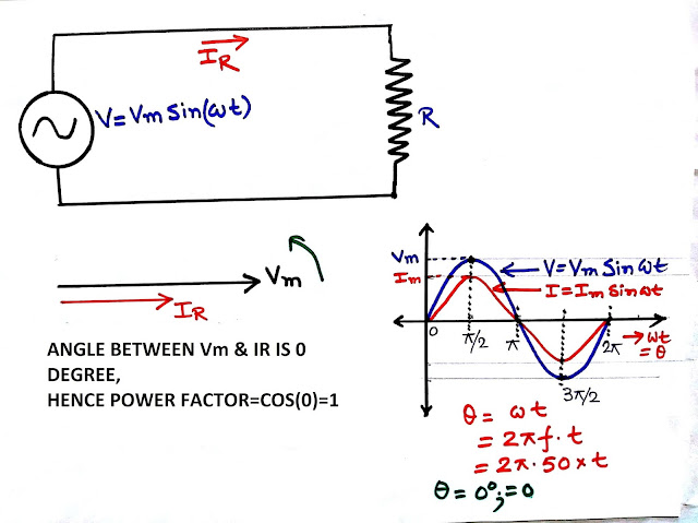
If a pure resistance is fed with a voltage then the voltage and current will be at the same phase hence power factor angle is 0 degrees so the power factor is cos(0)=1
For a purely inductive circuit, the phase angle between voltage and current shall be 90 degrees, where the current phasor will lag the voltage by 90 degrees, causing the power factor to be 0 lagging.

For a purely captive circuit the voltage will lag behind the current by 90 degrees, hence the current leading the voltage by 90 degrees, so here also the power factor angle is 90 degrees and the power factor is 0 but leading.

So, whether a power factor is leading or lagging shall be determined by the factor that the current is leading the voltage or lagging the voltage.
In practice, all electrical loads are inductive in nature, but they are not purely inductive but rather a combination of resistance and inductor. So their power factors are lagging but not 0.
In general, all electrical loads that have core material say the motor is designed for a power factor of 0.85 to 0.9. In our article, we shall presume that all electrical loads have a power factor of 0.85 lagging.
In industry, the motor is the major load, and they are the main culprit for low power factor. Apart from motors, there may be furnaces, heaters, etc. but being resistive load in nature they do not affect the power factor significantly.
In the article TRANSFORMER PHASOR DIAGRAM, we showed that a transformer also causes a lowering of power factor, i.e. if the load end power factor of a transformer is 0.8 source power factor will be less than 0.8. So the transformer also reduces the power factor to some extent. This type of electrical component reduces the power factor.
So it is okay that the Cosine of the angle between voltage and current is the power factor. But what is its significance? Suppose we say a motor is rated as 85 kW, 0.85 p.f (85 kW is just taken for simplicity of calculation, however, 85 kW is not a standard motor rating) what shall it mean?
It means that the active power output is 85 kW, but it shall draw some more power from the supply, we presume the motor has 100% efficiency, so output and input are the same.
The motor shall draw 85/0.85=100kVA power between which 80 kW is active power. But these 80 kW and 100 kVA are not linearly related, but they have a vector relation.
We shall have a component of
(100^2-85^2)^0.5=52.68
This is the reactive power.
Now if efficiency is 90% instead then the kW drawn from the supply shall be
=85/0.9=94.44kW
KVA from supply=100/0.9=111.11 kVA &
kVAr from supply=52.68/0.9=58.53 kVAr.
Also (94.44^2+58.53^2)^0.5=111.11
So we can see that to deliver a certain amount of active power we need some reactive power. The ratio of active power to apparent power (kW/kVA) is called the power factor.
The better-designed machine shall have a higher power factor hence the low requirement of reactive power. But it can never be zero.
Because all Electrical machines supply power by electromagnetism. So a certain amount of power is required for the machine core to get magnetized. This power doesn’t give any active output but it is necessary to give active output, hence it is called reactive power.
The core coils form an inductive circuit, hence the magnetizing current is always lagging in nature, causing reactive power demand of a machine.
Both the reactive and active power is drawn from the source. Our aim shall be to improve the source power factor, i.e. reducing reactive power demand from the source.
Because a low power factor causes a penalty to the industry, i.e. supply authority charges more money for a lower power factor, and for a high power factor i.e. 0.99 supply authority gives an award to the consumers.
So if we can supply the kVAr demand locally, our system will draw less kVAr from the source, so the power factor will be improved.
As the capacitor draws a leading current it injects reactive power into the system. So the addition of a capacitor in parallel to the load will increase the system power factor. Let’s see the below images.
Power Factor Improvement

From the above images, we can understand how capacitor improves power factor.
Now we have to size the capacitor. This means we have to determine the kVAr rating of a capacitor.
Power Factor Improvement

Suppose our system is running at a power factor of 0.85, and we want to improve it to 0.99
So from Fig-5 as shown above
ϴ1=Cos-1(0.85) =31.78 degree
ϴ2=Cos-1(0.99)=8.11 degree
KVAr1=kW*Tan(ϴ1)
KVAr2=kW*Tan(ϴ2)
KVAr Cap=KAVr1-KVAr2
=kW*(Tan(ϴ1)-Tan(ϴ2))
The selected capacitor kVAr rating shall be of the nearest round figure.
The power system Single line diagram shall be like below.

Power Flow before and after capacitor placement.

So this is the technique by which we can calculate the capacitor kVAr to improve the system power factor from a certain value to our desired one.
Advantages
- By varying the field excitation, the magnitude of the current drawn by the motor can be changed by any amount. This helps in achieving step-less control of the power factor.
- The motor windings have high thermal stability to short circuit currents.
- The faults can be removed easily.
Disadvantages
- There are considerable losses in the motor.
- The maintenance cost is high.
- It produces noise.
- Except in sizes above 500 kVA, the cost is greater than that of static capacitors of the same rating
- As a synchronous motor has no self-starting torque, therefore, auxiliary equipment has to be provided for this purpose.
