
PASSIVE ELEMENTS
A passive component only absorbs energy or absorbs energy and then later releases it.
Main three types of passive components are:
1. Resistor
2. Capacitor
3. Inductor
· RESISTANCE
Definition:
“The hindrance or opposition offered by the atoms of a conductor in the flow of electric current is called Resistance.”
Or
“It is a ratio of the potential difference to the current.”
Symbol:
Resistance is designated by the symbol R.
Unit:
The unit of measurement for resistance is ohms.
Factors on which resistance depends:
The amount of resistance depends upon
1. Length
2. Cross-section
3. Temperature
4. Nature of the substances
OHM’S LAW DEFINES RESISTANCE:
In 19th century, German mathematician, George Simon Ohm gave the following law: “Voltage across the conductor is directly proportional to the electric current passes through a conductor.”
V α I
V = I R
The relationship between current and voltage can be represented as,

Figure 1 v-I relationship of an ideal resistor
OHM’S LAW TRIANGLE
There is an easy way to remember which formula to use.

COMBINATION OF RESISTANCES:
1. Serial Combination:
- It is formed when any number of resistors are connected in a circuit end-to-end so that there is only one path for current to flow.
- The total or equivalent resistance is always larger than the individual resistance.
- Current is the same anywhere it is measured in a series circuit.
Total or equivalent resistance (Req) can be calculated as,
Req = R1 + R2 + R3 +…………………
2. Parallel Combination:
· It is formed when two or more resistances are placed side-by-side so that current can flow through more than one path.
· The total or equivalent resistance is always smaller than any individual resistance
· Voltage is the same anywhere it is measured in a parallel circuit
Total or equivalent resistance (Req) can be calculated as,
Circuit Symbol:
Two ways are:

Units of Measurement
Special prefixes that are commonly used when dealing with values of resistance:
| Prefix | Symbol | Decimal |
| 1 kilo ohm | 1 KΩ | 1000 Ω |
| 1 mega ohm | 1 MΩ | 1,000,000 Ω |
COLOR CODING:
SOME OF THE DIFFERENT TYPES OF RESISTORS USED ARE:
· Axial
· Surface mount
CAPACITOR
The capacitor is made of two metal plates with separated by insulating material. When a voltage is applied to the plates, electrons are forced onto one plate. The plate with an excess of electrons is negatively charged. The plate with a deficiency of electrons is positively charged.

Symbol: Capacitor is designated by the symbol C. Unit: The unit of measurement for the capacitor is Farad (F).
Factors on which capacitance depends:
The amount of capacitor depends upon
1. Area of the plates
2. Distance between the plates
3. Material of the dielectric
Simple Capacitive Circuit
In the following circuit, initially, the switch is open and no voltage is applied to the
Capacitor and when the switch is closed, the potential across the capacitor will rise rapidly at first, then more slowly as the maximum value is approached.

Combination of Capacitors:
1. Serial Combination:
- It is formed when any number of capacitors are connected in a circuit end-to-end so that there is only one path for current to flow.
- The total or equivalent capacitor is always smaller than the individual capacitor.
- Current is the same anywhere it is measured in a series circuit.
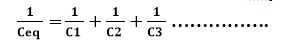
Total or equivalent capacitance (Ceq) can be calculated as,
2. Parallel Combination:
- It is formed when two or more capacitors are placed side-by-side so that current can flow through more than one path.
- The total or equivalent capacitor is always larger than any individual capacitor.
- Voltage is the same anywhere it is measured in a parallel circuit.
Total or equivalent resistance (Ceq) can be calculated as,
Ceq = C1 + C2 + C3 +…………………
Circuit Symbol:
Two ways are:

· INDUCTOR
Definition:
Inductance is the property of an electric circuit that opposes any change in electric current.
Inductance opposes the change in current flow.
Symbol:
Inductance is designated by the letter “L”.
Unit:
The unit of measurement for inductance is Henry (H).
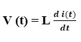
Expression:
The relationship between the time-varying voltage across an inductor L and the time-varying current passing through it can be expressed as,
Factors on which inductance depends:
The amount of inductance depends upon
1. Number of turns in the coil
2. Spacing between the turns
3. Coil diameter
4. Core material
5. Type of winding

Examples:
Examples are:
1. Transformers
2. Chokes
3. Motors
Simple Inductive Circuit
If an inductor is used, the current does not change as quickly. In the following circuit, initially, the switch is open and there is no current flow when the switch is closed, the current will rise rapidly at first, then more slowly as the maximum value is approached.
Circuit Symbol:
Two ways are:
Combination of Inductances:
1 Serial Combination:
· It is formed when any number of inductors are connected in a circuit end-to-end so that there is only one path for current to flow
· The total or equivalent inductance is always larger than the individual inductance
· Current is the same anywhere it is measured in a series circuit
Total or equivalent resistance (Leq) can be calculated as,
Leq = L1 + L2 + L3 +…………………
2. Parallel Combination:
· It is formed when two or more inductance are placed side-by-side so that current can flow through more than one path
· The total or equivalent inductance is always smaller than any individual resistance
· Voltage is the same anywhere it is measured in a parallel circuit
Total or equivalent resistance (Leq) can be calculated as,

Also read,
