OPERATING MODES OF THYRISTOR CONTROLLED SERIES COMPENSATOR (TCSC)
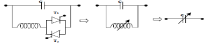
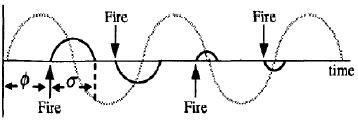
TCSC is used to decrease or increase overall effective series transmission impedance from sending end to the receiving end so as to control the transmission of power and the current in the reactor can be controlled from zero to maximum by the method of firing delay angle. Closure of the thyristor valve is delayed w.r.t. peak of the applied voltage in each half cycle thus the duration of the current conduction interval is controlled.
 |
| Figure 1: Operation of thyristor with various firing and conduction angles. |
There are three modes of operation of TCSC depending upon the firing angle of the pulses fed to the thyristor.
1) Thyristor-blocked mode
2) Thyristor bypassed mode
3) Vernier operating mode
1) THYRISTOR BLOCKED OPERATING MODE:
When the thyristor valve is not triggered and the TCSC is operating in blocking mode. In this mode, the TCSC performs like a fixed-series capacitor.
2) THYRISTOR BYPASS OPERATING MODE:
In bypass mode, the thyristor valve is triggered continuously and the valve stays conducting all the time; so the TCSC behaves like a parallel connection of the series capacitor with the inductor, Ls in the thyristor valve branch. In this mode, the resulting voltage in the steady state across the TCSC is inductive and the valve current is somewhat bigger than the line current due to the current generation in the capacitor bank. For practical UCSCs with a ratio (XL/XC) between 0.1 to 0.3 ranges, the capacitor voltage at a given line current is much lower in bypass than in blocking mode. Therefore, the bypass mode is utilized as a means to reduce the capacitor stress during faults.
3) VERNIER OPERATING MODE:
In Vernier’s control, the TCSC dynamics are varied continuously by controlling the firing angle. The firing angle is possible from 0o to 90o for each half cycle when it is generated from the zero crossing of the line current hence divided into two parts:
1) Capacitive Boost mode
2) Inductive Boost Mode
1) CAPACITIVE BOOST MODE:
In capacitive boost mode, a trigger pulse is supplied to the thyristor having forward voltage just before the capacitor voltage crosses the zero line, so a capacitor discharge current pulse will circulate through the parallel inductive branch. The discharge current pulse adds to the line current through the capacitor and causes a capacitor voltage that adds to the voltage caused by the line current. The capacitor peak voltage thus will be increased in proportion to the charge that passes through the thyristor branch. The fundamental voltage also increases almost proportionally to the charge. From the system point of view, this mode inserts capacitors to the line up to nearly three times the fixed capacitor. This is the normal operating mode of TCSC.
2) INDUCTIVE BOOST MODE:
In inductive boost mode, the circulating current in the TCSC thyristor branch is bigger than the line current. In this mode, large thyristor currents result and further the capacitor voltage waveform is very much distorted from its sinusoidal shape. The peak voltage appears close to the turn-on. The poor waveform and the high valve stress make the inductive boost mode less attractive for steady-state operation.
COMPARISON OF FACTS DEVICES IN AC SYSTEMS:
There are various types of FACT controllers in the market having their own advantages depending upon their individual characteristics. Here comparison study has been done on different FACT controllers to study their impact on various applications. (* Small, ** Medium, *** Strong).
| FACTS DEVICE | Power Flow | Voltage Control | Transient Stability | Oscillation Damping |
| SVC | * | *** | * | ** |
| STATCOM | * | *** | ** | ** |
| TCSC | ** | * | *** | ** |
| SSSC | *** | * | *** | ** |
| UPFC | *** | *** | *** | *** |
Related Topic – click here
- What Is A Diode? Working Principle & Types | Different Types Of Resistors
- What Is Synchronous Speed? | Types & Advantages Of DC Motors
- Working Principle Of Linear Variable Differential Transformer | Construction & Piezoelectric Transducers
- Three-Phase Induction Motor | 3-Phase Induction Motor Principle
- Introduction To Electrical Transformer | Definition, Construction & Parts Of A Transformer | Types Of Transformers
- DC Generator | Principle Of Operation, Construction, Types Of Generators & Application
- What Is DC Motor? | Principle Of DC Motor & Types Of DC Motors
- Diode-Circuits |Diode Convention, Transformer Rectifier & Objective Questions With Answer


