
solar power system
Solar systems must require measuring instruments to provide various readings to the user. In this article, we are going to introduce the instruments which are used for measuring purposes in solar systems. Solar systems are commonly made up of many devices like Charge controllers, Solar Panels, Inverters, Batteries, etc. To assemble these devices, wire is used with a specific diagram. In the process of installation of Solar systems, Protection Devices, as well as Measuring Instruments, are also used to protect all the systems installed. The following are the measuring instruments that are used and installed in Solar Systems.
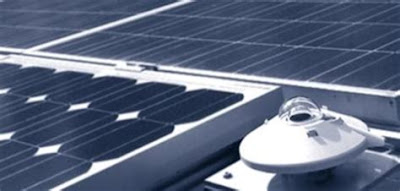
Pyranometer
Pyranometers are used to measure the radiation energy of solar systems from the entire hemisphere. This meter has a wide range of its applications in climate research, solar-thermal, agriculture, Photovoltaic research, and many other development applications.

A pyranometer is used to measure broadband solar irradiance on a planner surface and as a sensor to measure the solar radiation flux density(W/m2)from a view of 180 degrees.
Usage
Pyranometers are commonly used in meteorology, solar energy studies, and climatology. these meters are installed in many meteorological stations and can be seen easily in meteorological stations. These meters are installed horizontally and next to solar panels and mounted with the sensor surface in the plane of the panel.
Explanation
The range of the solar radiation spectrum is approximately from 300nm to 2800nm.These meters cover that spectrum with a spectral sensitivity that is as flat as possible.To measure the irradiance of PV panel,hit the meter’s sensor perpendicular to the to the surface when sun is at horizon.Then the pyranometer will provide the directional response which will be near to its ideal characteristics.
Voltmeter
A voltmeter is an instrument used to measure the electric potential difference between two points in an electric circuit. Voltmeter consists of two types, Analog and Digital Voltmeters. Analog voltmeters move the pointer across a scale with respect to the voltage of the device or circuit while Digital Voltmeters give the numerical display of the voltages of the circuit or the device on a screen by using analog to digital converter.

Voltmeters are made in a wide range of its styles. Meters that are permanently mounted in a panel are always used to provide the value of the fixed apparatus or of a fixed device. Portable instruments are used to measure the current, resistance, and voltages in the form of multimeters which are the standard testing instruments for electrical and electronic work.
Analog Voltmeters have an accuracy of a few percent of their full scale and are used with a fraction of a volt to several volts. Digital Voltmeters are made with high accuracy. these meters are better than 1%. Especially test instruments have higher accuracies than lab instruments. Meters that are used in amplifiers can measure tiny voltages of very small amounts.
Ampere meters
Current is a measure of the rate of flow of electrons in a circuit. It is measured in the unit of Ampere called “Amp” and is denoted by (A).To measure the current of any circuit, connect the ampere meter in series and it will provide the rating. Ampere meters are always connected in series with the circuit so that all the electrons flowing through the circuit also have to go through the meter. It is very difficult to measure the current as compared to voltage or resistance.

When an ammeter is connected in series with a circuit, it does not drop voltages as current goes through it. It acts like a piece of wire which consists of very little resistance from one test probe to another. If the ammeter is placed parallel to the circuit, it will act like a short circuit across the terminals and a surge will damage the meter.
Ohm meter

An Ohmmeter is an electrical instrument that measures electrical resistance(opposition of an electric current). Micro Ohmmeters can measure a low amount of resistance whereas Mega Ohmmeters can measure a high amount of resistance. The unit of measurement for resistance is ohm(Ω).
Watt meter

A watt meter is an instrument that is used to measure the electric power in watts of any electric circuit. Electromagnetic watt meters are used for the measurement of frequencies. A modern electronic wattmeter samples the voltage and current thousands of times a second. Wattmeters provide readings in RMS current, VA, power, power factor, and kilowatt hours. The reading is displayed on the screen of the device. Wattmeters vary considerably in correctly calculating energy consumption especially when real power is much lower than VA. Watt meters consist of two types named analog and digital. Analog meters cannot provide the exact values or observations whereas digital meters provide the exact value with no error.
Tong tester

A tong tester is an electric meter used in electrical and electronics engineering. It consists of two jaws that open to allow clamping around an electrical conductor. These type of meters allows us to measure the electric current of the conductor without making physical contact. Tong testers are also called current clamps and these clamps are used to read the magnitude of a sinusoidal current. by using this meter a large amount of current can be measured very easily rather the current is alternating or direct. These types of meters consist of two types: Analog and Digital current clamp. Analog meters have low accuracy whereas digital meters consist of high accuracy.


