
What is an LC circuit?
LC circuit is a key component in many electronic devices, such as oscillators and filters that help to generate oscillations. The capacitor stores energy between its two plates in the electric field, while the inductor stores it in its magnetic field.
The operating frequency in Hertz of the LC oscillator is given by:
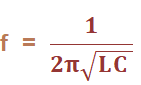
Where,
L is the inductance measured in Henry.
C is the capacitance measured in Farads
The unit of frequency is Hertz.
Here, we will discuss the types of LC oscillators, and their advantages and disadvantages.
There are three types of LC oscillators, which are as follows:
- Hartley Oscillator
- Colpitts Oscillator
- Clapp Oscillator
Advantages of LC oscillators
The advantages of LC oscillators are as follows:
- High phase stability
The LC oscillator produces good stability at high frequencies. It is because the operating frequency of the oscillator does not change much with temperature change. - Low noise
It is due to the inductors and capacitors in the feedback network. - High Q-factor
The LC oscillators have a high Quality-factor as compared to other oscillators.
Disadvantages of LC oscillators
The disadvantages of LC oscillators are as follows:
- The change in temperature affects the components, such as transistors, capacitors, resistors, supply voltages, and the inductor of the circuit.
- The operating frequency of the oscillator is not constant. It is due to the various components involved in the circuit.
- The operating frequency can shift if any component in the feedback circuit is changed.
- It is not suitable at low frequencies. At low frequencies, the capacitor and inductor do not work well and produce instability in the circuit.
- High cost.
Limitations Of Lc And Rc Oscillators
The LC and RC oscillators have their own limitations. The major problem in such circuits is that their operating frequency does not remain strictly constant. There are two principal reasons for this viz.,
- As the circuit operates, it will warm up. Consequently, the values of resistors and inductors, which are the frequency-determining factors in these circuits, will change with temperature. This causes a change in the frequency of the oscillator.
- If any component in the feedback network is changed, it will shift the operating frequency of the oscillator.
However, in many applications, it is desirable and necessary to maintain the frequency constant with extremely low tolerances. For example, the frequency tolerance for a broadcasting station should not exceed 0.002% i.e. change in frequency due to any reason should not be more than 0.002% of the specified frequency. The broadcasting stations have frequencies that are quite close to each other. In fact, the frequency difference between the two broadcasting stations is less than 1%.
It is apparent that if we employ LC or RC circuits, a change in temperature may cause the frequencies of adjacent broadcasting stations to overlap. In order to maintain a constant frequency, piezoelectric crystals are used in place of LC or RC circuits. Oscillators of this type are called crystal oscillators. The frequency of a crystal oscillator changes by less than 0.1% due to temperature and other changes. Therefore, such oscillators offer the most satisfactory method of stabilizing the frequency and are used in the great majority of electronic applications.
Limitations Of Lc And Rc Oscillators
LC (Inductor-Capacitor) oscillators and RC (Resistor-Capacitor) oscillators have the following limitations:
- LC Oscillators:
- Limited frequency range: LC oscillators are limited to low and medium-frequency applications.
- High Q factor requirements: The oscillator requires a high Q factor inductor, which may be expensive and bulky.
- RC Oscillators:
- Limited frequency stability: RC oscillators tend to have limited frequency stability, as the resistance in the circuit can vary with temperature changes and other factors.
- Limited output power: RC oscillators have limited output power, which may limit their usefulness in some applications.
- Both:
- Sensitivity to component tolerance and stability: Both LC and RC oscillators are sensitive to variations in component values, which can result in variations in oscillator frequency and stability.
- Difficulty in frequency tuning: LC and RC oscillators can be difficult to tune to a specific frequency, especially in applications where precise frequency control is required.
Related topic – click here
- Types Of Losses In Transformer Explained
- Differences Between 8085 And 8086 Microprocessor
- 8085 Microprocessor Architecture | Working On 8085 Microprocessor
- Difference Between Single-Phase And Three-Phase Transformer
- Water Filter Essential For Purification Of Drinking Water
- Thermocouple Types And Comparison | Thermocouple Of 8000-Liter Storage Tank