INTERLINE POWER FLOW CONTROLLER (IPFC)
Recent developments in FACTS research have led to a new device: the Interline Power Flow Controller (IPFC). This element consists of two (or more) series voltage source converter-based devices (SVSC) installed in two (or more) lines and connected at their DC terminals. Thus, in addition, to serially compensating the reactive power, each SSSC can provide real power to the common DC link from its own line.
The IPFC gives them the possibility to solve the problem of controlling different transmission lines at a determined substation. In fact, the under-utilized lines make available a surplus power that can be used by other lines for real power control. This capability makes it possible to equalize both real and reactive power flow between the lines, to transfer power demand from overloaded to underloaded lines, to compensate against resistive line voltage drops and the corresponding reactive line power, and to increase the effectiveness of a compensating system for dynamic disturbances (transient stability and power oscillation damping). Therefore, the IPFC provides a highly effective scheme for power transmission at a multi-line substation. The IPFC is a multi-line FACTS device.
 PIN IT PIN IT |
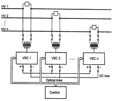
| Figure 1: Schematic diagram of IPFC |
An Interline Power Flow Controller (IPFC) consists of a set of converters that are connected in series with different transmission lines. The schematic diagram of IPFC is illustrated in Figure 1. In addition to these series converters, it may also include a shunt converter which is connected between a transmission line and the ground. The converters are connected through a common DC link to exchange active power. Each series converter can provide independent reactive compensation of its own transmission line. If a shunt converter is involved in the system, the series converters can also provide independent active compensation; otherwise, not all series converters can provide independent active compensation for their own line.
Compared to the Unified Power Flow Controller (UPFC), the IPFC provides a relatively economical solution for multiple transmission line power flow control, since only one shunt converter is involved. The IPFC also gains more control capability than the Static Synchronous Series Compensator (SSSC), which is like the IPFC but without a common DC link, because of the active compensation. From a probabilistic point of view, the performance of the IPFC will be better when more series converter is involved in the IPFC system.
However, because the converters are connected through the common DC link, the converters should be physically close to each other. The common DC link will become a location constraint for the IPFC and limit its commercial application in the future network. Therefore, a method that can eradicate the IPFC common DC link and provide the active power exchange between converters will be interesting.
Advantages of IPFC (INTERLINE POWER FLOW CONTROLLER)
- Essentially, IPFC can protect power system equipment from overloading and under-loading of transmission lines.
- Enhance protection by minimizing contactor wear and tear.
- Reduces the degree of field failures.
- In case of harmonic distortion such as voltage and current distortion, it can switch off the system through any of the Voltage Source Converters.
- On the occurrence of faults, VSCs shut off capacitor banks.
- Avoid PF penalties through proper reactive compensations.
- Faulty operation through manual control is minimized, which also prevents switching devices manually.
- On any system, failure monitoring and signaling are enhanced and clear alarm.
Disadvantages of IPFC (INTERLINE POWER FLOW CONTROLLER)
- On series voltage injection, the IPFCs can make the voltages in nonstiff buses cross their bus voltage operating limits. This causes proscribed overvoltages and damages the system equipment.
- The transmission angle increase or decrease for the compensating line affects the line current in the uncompensated line. Hence, it has a negative impact on the uncompensated lines.
- Since the VSCs used in the system almost have the same capacity, the control area of the compensating converter remains limited. For instance, the converter VSC-2 cannot compensate for both lines.
- Imposes limitation in the operative series compensation voltage because of the technical limits.
Applications of IPFC (INTERLINE POWER FLOW CONTROLLER)
- Transient Stability improvement.
- Employed in Power Transmission system.
- Low-frequency oscillations damping.
- Control power oscillation dampings.
- Improves voltage stability.
- Reactive and real power flow control.
- Enhanced for rotor angle stability.
- Equalize both real and reactive power.
Related Topic – click here
- What Is A Diode? Working Principle & Types | Different Types Of Resistors
- What Is Synchronous Speed? | Types & Advantages Of DC Motors
- Working Principle Of Linear Variable Differential Transformer | Construction & Piezoelectric Transducers
- Three-Phase Induction Motor | 3-Phase Induction Motor Principle
- Introduction To Electrical Transformer | Definition, Construction & Parts Of A Transformer | Types Of Transformers
- DC Generator | Principle Of Operation, Construction, Types Of Generators & Application
- What Is DC Motor? | Principle Of DC Motor & Types Of DC Motors
- Diode-Circuits |Diode Convention, Transformer Rectifier & Objective Questions With Answer
