
• It requires two internal address and they are A =0 or A = 1.
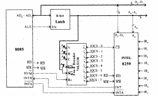
• It can be either memory-mapped or I/O-mapped in the system. The interfacing of 8259 to 8085 is shown in the figure is I/O mapped in the system.
• The low order data bus lines D0-D7 are connected to D0-D7 of 8259.
• The address line A0 of the 8085 processor is connected to A0 of 8259 to provide the internal address.
• The 8259 requires one chip select signal. Using a 3-to-8 decoder generates the chip-select signal for
8259.
• The address lines A4, A5 and A6 are used as input to decoder.
• The control signal IO/M (low) is used as logic high enables for the decoder and the address line A7 is used as logic low enables for a decoder.
• The I/O ad4ressès of 8259 are shown in table-8.5.

• First the 8259 should be programmed by sending Initialization Command Word (ICW)
and Operational Command Word (OCW). These command words will inform 8259 about the following,
* Type of interrupt signal (Level triggered / Edge triggered).
* Type of processor (8085/8086).
* Call address and its interval (4 or 8)
* Masking of interrupts.
* Priority of interrupts.
* Type of end of interrupts.
• Once 8259 is programmed it is ready for accepting interrupt signals. When it receives an interrupt through any one of the interrupt lines IR0-IR7 it checks for its priority and also checks whether it
is masked or not.
• If the previous interrupt is completed and if the current request has the highest priority and is unmasked, then it is serviced.
• For servicing this interrupt the 8259 will send an INT signal to the INTR pin of 8085.
• In response it expects an acknowledged INTA (low) from the processor.
• When the processor accepts the interrupt, it sends three INTA (low) one by one.
• In response to the first, second, and third INTA (low) signals, the 8259 will supply the CALL opcode, the low byte of the call address, and the high byte of the call address respectively. Once the processor receives the call opcode and its address, it saves the content of the program counter (PC) in a stack and loads the CALL address in the PC, and starts executing the interrupt service routine stored in this call address.


