
GENERATOR ROTOR PROTECTION
There are several different types of rotor protection, each type guarding the rotor against a particular type of fault. From this viewpoint, the protection against unbalanced loading, using negative sequence relays, can be considered a type of rotor protection since the effect of negative sequence currents is likely to result in rotor damage.
1) SHORTED FIELD WINDING PROTECTION
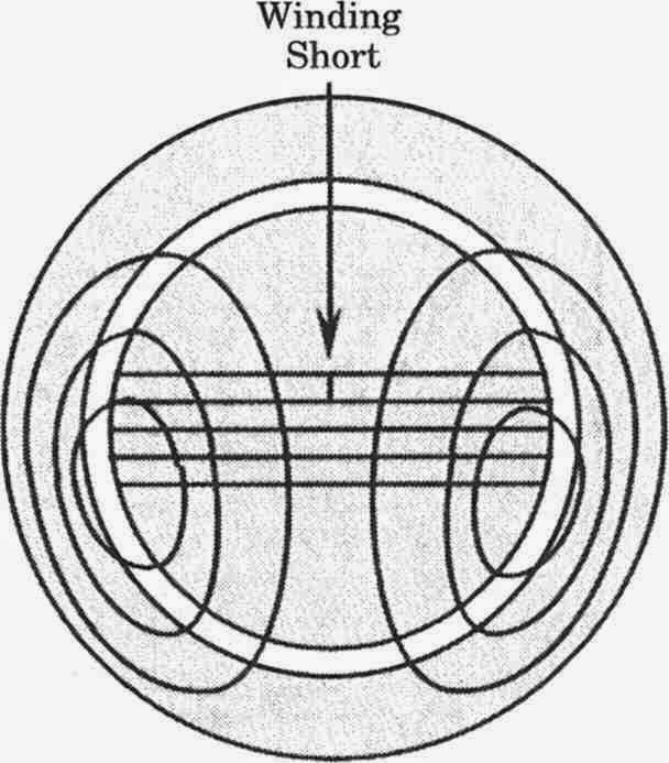
Shorted turns in the generator field winding have the potential for distorting the field across the air gap, as illustrated in Figure 1. This is due to the unsymmetrical ampere-turns of mmf in different parts of the field winding. If the air gap flux is badly distorted, there can be many distorted forces acting on the rotor, since the forces vary as the square of the flux density.
Once there are unequal forces on opposite sides of the rotor, there is a tendency for the rotor to warp. The unbalanced force can be very large, as much as 50 to 100 tons, tending to warp the rotor. In some cases, the rotor may be displaced enough to contact the stator iron core.
.jpg) |
| Figure 1: Field flux pattern with shorted field |
Another effect of the unbalanced forces on the rotor is severe vibration, which may cause damage to the bearings. The machine can be spared from serious damage by vibration detectors, which can alarm the operator or trip the unit. The mechanism that causes the shorted winding is often due to the grounding of the winding at two different places.
2) GROUNDED FIELD WINDING
The field winding of a synchronous machine is usually floating with respect to the ground. A single ground fault, therefore, does not draw any fault current, although it does stress the insulation in portions of the winding. The real danger is a second ground, which can set up significant forces. Dual grounds can also draw very large currents and may cause extensive damage to the field conductor and rotor steel. The best way to prevent this from occurring is to detect the first ground, thereby preventing a more serious chain of events.
The generator main and field breakers should be tripped on the occurrence of the first ground. The exception is in attended stations, where the unit trip may be delayed until a more convenient time to schedule the repair. During this period, any unusual vibration should immediately trip the unit. It is best to not trip the turbine following a rotor ground fault and tripping the generator and field.
The rotor has better cooling when running at rated speed, and the excess heat is carried away as the generator continues to run for several minutes at rated speed. Allowing the unit to coast down also introduces the danger of aggravated vibration due to natural modal frequencies of vibration, which may be worse due to rotor distortion.
There are several methods of detecting a rotor circuit ground. The methods, shown in Figure 2, are summarized as
1. Potentiometer method
2. AC injection method
3. DC injection method
 |
| Figure 2: Methods of detecting field winding grounds. (a) Potentiometer method. (b) AC injection method. (c) DC injection method. |
The POTENTIOMETER METHOD measures the voltage to the ground of a center-tapped resistor, connected across the exciter output voltage. If some point in the winding becomes grounded, there will be a potential between that point and the point to which the voltage relay is connected.
The only problem is that should a point very close to the center of the winding become grounded, the center-tapped potentiometer would not detect it. To check that this has not happened, a manual switch is arranged to move the test point from the center to some other point along the resistor. The operator can check this periodically to ensure that the system is sound.
A better method is the AC INJECTION METHOD, which connects an AC voltage to the field winding through a capacitor. Should any point on the field winding become grounded, the circuit will be complete and the relay will trip. This system has no blind point. There is a disadvantage, however, in that some current will flow through the capacitance from the field winding to the rotor body, through the rotor body, the bearings, and to the ground. This has the potential of causing erosion of the metal in the bearings.
A still better method is the DE INJECTION METHOD. The de-output of the transformer-rectifier unit is connected to bias the positive side of the field circuit to a negative voltage relative to the ground. A ground at any point on the field winding will complete the circuit to the grounded side of the relay. The relay is a sensitive current relay in this case, but must not be so sensitive that it will trip due to normal insulation leakage current. The current through the relay is limited by the high impedance of the rectifier.
A special problem is presented in the case of the brushless exciter. This exciter is an alternator-rectifier exciter that is physically on the rotor and rotating at synchronous speed.
The field for the alternator is stationary. The basis of the design is that there is no need for brushes between the field winding and the casing of the machine. In this type of exciter, there is usually no access to the field circuit; therefore, the previous types of ground detectors will not work. The only portion of the excitation system that is accessible to the outside is the field of the alternator exciter. Any severe fault oil in the field winding will require excess field current, hence excess excitation for the alternator rectifier. The backup is a vibration monitor that can take action if a severe field winding fault occurs.
3) OPEN-FIELD WINDING
The field winding open circuits are rare, but prompt action is required when an open occurs because it will be accompanied by arcing that can do great damage to the rotor iron. An open circuit that does not involve ground will cause a sudden drop in field current that can be detected by a loss-of-field relay.
4) OVERHEATING OF THE FIELD WINDING
The temperature of the field winding can be monitored by an ohmmeter type of detector that measures the winding resistance of the field. Such an instrument is often calibrated in temperature, rather than ohms, for a direct estimation of the winding temperature.
Related topic – click here
- Types Of Losses In Transformer Explained
- Differences Between 8085 And 8086 Microprocessor
- 8085 Microprocessor Architecture | Working On 8085 Microprocessor
- Difference Between Single-Phase And Three-Phase Transformer
- Water Filter Essential For Purification Of Drinking Water
- Thermocouple Types And Comparison | Thermocouple Of 8000-Liter Storage Tank