
Electrodynamometer Wattmeter – Construction and Working
An electrodynamometer wattmeter is an electrical measuring instrument that is used to measure the power in an AC electrical circuit. It is based on the principle of electromagnetic induction.
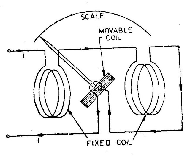
Construction:
The construction of an electrodynamometer wattmeter typically consists of a moving coil, a stationary coil, and a pointer. The moving coil is connected to the current-carrying conductor and rotates in the magnetic field of the stationary coil, which is connected to the voltage-carrying conductor. The pointer is attached to the moving coil and indicates the power measurement on a scale.
Working:
The working of an electrodynamometer wattmeter involves the interaction of the current-carrying conductor and the voltage-carrying conductor, with the resulting electromagnetic forces causing the moving coil to rotate. The angle of rotation is directly proportional to the power in the circuit.
The current-carrying conductor, which carries the current to be measured, is passed through the moving coil. The voltage-carrying conductor, which carries the voltage across which power is to be measured, is passed through the stationary coil. The two coils are positioned in such a way that their fluxes oppose each other. The current-carrying conductor cuts the flux set up by the stationary coil, thus inducing a current in the moving coil, which in turn sets up a flux that opposes the flux set up by the stationary coil. This interaction causes the moving coil to rotate. The angle of rotation is proportional to the product of the current and voltage and can be read from the scale of the wattmeter.
It should be noted that the electrodynamometer wattmeter has a limited range of measurement and is typically used for measuring power in medium to high-voltage circuits.
Electrodynamometer Type
• The necessity for the a.c. calibration of moving iron instruments as well as other types of instruments, which cannot be correctly calibrated, requires the use of a transfer type of instrument.
• A transfer instrument is one that may be calibrated with a d.c. Source and then used without modification to measure a.c.
• This requires the transfer type instrument to have the same accuracy for both d.c. and a.c., which the electrodynamometer instruments have.
• These standards are precision resistors and the Weston standard cell (which is a d.c. cell).
• It is obvious, therefore, that it would be impossible to calibrate an a.c. instrument directly against the fundamental standards.
• The calibration of an a.c. the instrument may be performed as follows.
• The transfer instrument is first calibrated on d.c.
• This calibration is then transferred to the a.c. the instrument on alternating current, using operating conditions under which the latter operates properly.
• Electrodynamics instruments are capable of serving as transfer instruments.
• Indeed, their principal use as ammeters and voltmeters in laboratory and measurement work is for the transfer calibration of working instruments and as standards for calibration of other instruments as their accuracy is very high.
• Electrodynamometer types of instruments are used as a.c. voltmeters and ammeters both in the range of power frequencies and lower part of the audio power frequency range. They are used as wattmeters, voltmeters, and with some modifications as power factor meters and frequency meters.
Operating Principle
• It would have a torque in one direction during one half of the cycle and an equal effect in the opposite direction during the other half of the cycle.
• If the frequency were very low, the pointer would swing back and forth around the zero point.
• However, for an ordinary meter, the inertia is so great that on power frequencies the pointer does not go very far in either direction but merely stays (vibrates slightly) around zero.
• If, however, we were to reverse the direction of the flux each time the current through the movable coil reverses, a unidirectional torque would be produced for both positive and negative halves of the cycle.
• In electrodynamometer instruments the field can be made to reverse simultaneously with the current in the movable coil if the field (fixed) coil is connected in series with the movable coil.
Construction
Fixed Coils
• The field is produced by a fixed coil.
• This coil is divided into two sections to give a more uniform field near the center and to allow passage of the instrument shaft.
Moving Coil
• A single-element instrument has one moving coil.
• The moving coil is wound either as a self-sustaining coil or else on a non-metallic former.
• A metallic former cannot be used as an eddy current would be induced in it by the alternating field.
• Light but rigid construction is used for the moving coil.
• It should be noted that both fixed and moving coils are air-cored.
Control
• The controlling torque is provided by two control springs.
• These springs act as leads to the moving coil.
Moving System
• The moving coil is mounted on an aluminum spindle.
• The moving system also carries the counterweights and truss-type pointer.
• Sometimes a suspension may be used in case a high sensitivity is desired.
Damping
• Air friction damping is employed for these instruments and is provided by a pair of aluminum vanes, attached to the spindle at the bottom.
• These vanes move in sector-shaped chambers.
• Eddy current damping cannot be used in these instruments as the operating field is very weak (on account of the fact that the coils are air-cored) and any introduction of a permanent magnet required for eddy current damping would distort the operating magnetic field of the instrument.
Shielding
• The field produced by the fixed coils is somewhat weaker than in other types of instruments
• It is nearly 0.005 to 0.006 Wb/m
• In D.C. Measurements even the earth’s magnetic field may affect the readings.
• Thus it is necessary to shield an electrodynamometer-type instrument from the effect of stray magnetic fields.
• Air-cored electrodynamometer-type instruments are protected against external magnetic fields by enclosing them in a casing of high permeability alloy.
• This shunts external magnetic fields around the instrument mechanism and minimizes their effects on the indication.
Cases and Scales
• Laboratory standard instruments are usually contained in highly polished wooden cases.
• These cases are so constructed as to remain dimensionally stable over long periods of time.
• The glass is coated with some conducting material to completely remove the electrostatic effects.
• Adjustable leveling screws support the case.
• A spirit level is also provided to ensure proper leveling.
• The scales are hand drawn, using machine sub-dividing equipment.
• Diagonal lines for fine sub-division are usually drawn for main markings on the scale.
• Most of the high-precision instruments have a 300 mr scale with 100, 120, or 150 divisions.
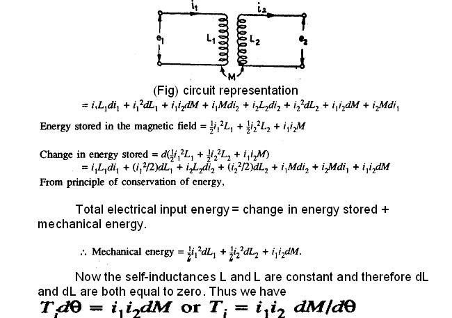
Torque Equation
Let,
i1 = instantaneous value of current in the fixed coils: A.
i2 = instantaneous value of current in the moving coil: A.
L1 = self-inductance of fixed coils: H.
L2 = self-inductance of moving coils H,
M = mutual inductance between fixed and moving coils:
Flux linkages of coil 1, ψ1 = L1 i1 + Mi2
Flux linkages f coil 2, ψ2 = L2 i2 + Mi1
Electrical input energy = e1i1dt+e2i2dt
Errors in Electrodynamometer Instruments
i) Frequency error
ii) Eddy current error
iii) External magnetic field
iv) Temperature changes
Advantages
i) These instruments can be used on both a.c & d.c
ii) Accurate RMS value
Disadvantages
(i) They have a low torque/weight ratio and hence have a low sensitivity.
(ii) Low torque/weight ratio gives increased frictional losses.
(iii) They are more expensive than either the PMMC or the moving iron-type instruments.
(iv) These instruments are sensitive to overloads and mechanical impacts. Therefore, they must be handled with great care.
(v) The operating current of these instruments is largely owing to the fact that they have a weak magnetic field. The flux density is about 0.006 Wb/m as against 0.1 to 0.5 Wb/m in PMCC instruments
(vi) They have a non-uniform scale.
Related Topic – click here
- Dynamometer Type Three-Phase Wattmeter
- Three Methods Of Compounding In Steam Turbines
- Classification Of Moving Iron Instruments
- CONSTRUCTION OF D.C. MACHINE
- Three-Point Starter Measuring Instruments
- Electrodynamometer (Electrodynamics) Type Instruments
- STATIC & DYNAMIC CHARACTERISTICS OF ELECTRICAL MEASUREMENT SYSTEM
- Starting Of Induction Motor | Types Of Three-Phase Induction Motor Starting Methods
- Electrical Engineering History Facts Words | History Of E


