
Distillation Column Diagram
A simple CAD diagram of a distillation column can explain how to draw the column for a basic calculation of the mechanical design of the structure, it is a rough diagram to have a view of the plates, manhole, condenser, heat exchanger, and supports to the column. you can modify this skeleton and have more complex accessories, by changing sieve plates and the height and width of the column in your CAD software which suits your project design.

A schematic drawing of the distillation column which is used to extract CO2 from NH3 from wastewater, bubble cap trays, and low-pressure steam is used for stripping. An operating temperature is about 190 0 centigrade, the operating pressure is 3.5 kg/cm2. SS304L (stainless steel) is used as the material of construction. The dimensions are 1600 mm inner diameter, 27200 mm tan to tan length, with 55 number bubble cap trays and 400 mm tray spacing.
A basic diagram of the distillation column should represent the number of trays, types of trays, the location of plates and their weir and downcomers diameter and plate diameter, manholes locations, basement, and its dimensions, inlet feed locations and distillate, reflux locations, reboiler types and vapor input. Distillation column diagrams differ from each mode of operation like continuous and batch.
In the case of catalyst distillation placement of the catalyst bed and the quantity of catalyst should be represented and the supporting tray’s diameter and thickness will add up the load to the distillation column. Load calculations are simulated based on the material of construction and design construction of the column will show the air swing of the column due to wind drag.
EFFECT IN TOWERS AND COLUMNS
Towers or columns are the equipment that is used in industrial operations for the separation and purification process. All most every chemical industries contain these columns varying in different sizes, and even in analytical operations, instruments such as HPLC (high-performance liquid chromatography columns)which are used for the separation of mixed components in the samples depend on the column design. Tray towers offer more pressure drop than packed towers. so, for simple separation tray towers which consist of trays or sieves are preferred over packed towers where a packing material is used instead of trays.
Overview of the Effects in a Column and Terminology :
All mechanical aspects which occur in a column are referred to as Effects in Tower, these mechanical problems are caused by the physical properties and the mechanism by which the column is operated by the control valves and inlet and outlet stream flow rates, even the structure and internal design also considered in this concept, we see some of the important and very well faced problem for every column, which is as shown with a comparison of ideal condition of sieve tray column:
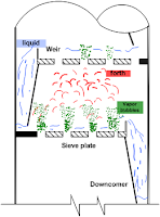
The blue color indicates = a liquid flow pattern
The green color indicates = the vapor flow pattern
The red color indicates forth
Flooding in a column
It occurs in a packed column due to a high-pressure drop. At the same gas flow rate, the pressure drop in a packed tower being irrigated with liquid is greater than in the dry packed tower. The operating velocity in a packed tower is usually equal to the flooding velocity. This effect can be well understood as simple as liquid filling up from the bottom of the column to the top and exhausting out from the top inlet of the column.
The point at which this effect occurs the velocities at which a column is operated is called flooding velocities. The downcomer and space between the trays are completely filled up by the liquid and the tower is said to be flooded, due to high-pressure drop due to increased flow rates of the streams.

Effects due to flooding:
1. Tray efficiency falls
2. The liquid may force out of the exit pipe at the tower top
Overall tray efficiency is defined as the ratio of the number of real trays required to the number of ideal trays required. Channeling is most severe in towers packed with stacked packing. Wetted wall tower experiments are used to determine the volumetric coefficient of two interacting phases.
Priming in a distillation column is desirable from point efficiency considerations. Priming is an exaggerated condition of liquid entrainment. The packed column provides a substantially smaller liquid hold-up as compared to the plate column. Outlet weirs (provided on the plate in a plate column) maintain the desired liquid level on the plate. Inadequately large weir height may cause all of the foregoing; a common weir height for absorbers and strippers is 3 to 4 inches. The binary liquid-liquid system has two degrees of freedom.
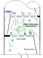
Due to high gas velocity, liquid from the bottom trays is carried away along with the vapor to the top trays.
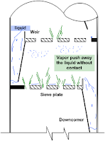
Coning is a Tray Tower
occurs due to low liquids flow velocities when compared to gas which results in the pushing of the liquid away from the tray openings.
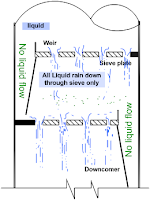
Weeping in a Sieve Tray Column
is due to a low gas velocity which is not equal to liquid flow velocity, and the liquid is not enough resisted to hold on to the tray pass from the downcomers, the complete liquid will flow through the openings in the tray itself. so, weeping occurs when gas velocities (in a plate column) are too low. Most of the liquid is rained down from tray openings and some through the downcomer.
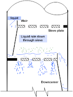
In the event of severe weeping, no liquid reaches the downspouts. Complete liquid drops down by the tray opening only. This phenomenon is known as dumping.
The gas hold-up is defined as the fraction of the liquid-gas mixture occupied by the gas.
Weber number is defined as the ratio of shear forces to inertial forces and the ratio of inertial forces to surface forces. Absorption factors are defined as mE/R.
The stripping factor is defined as R/ mE. The Marangoni effect is also known as interfacial turbulence.
The “capillary number” is (K L/ g) (g/GC) where K: permeability; : liquid surface tension; L: liquid density. Large depths on trays (reasonable gas velocities) in a tray column lead to high-pressure drop but high tray efficiencies. Recommended plate spacing for tower diameter of 12 to 24 ft is 36 inches.
A ternary liquid-liquid system has three degrees of freedom. In a countercurrent liquid-liquid extractor, slip velocity [Ud/ +UC/(1- )] where Ud and Uc are, respectively, dispersed and continuous phase superficial velocities and is the fractional dispersed phase hold-up) is Us. In a packed countercurrent extractor, slip velocity is Us’. The relation is Us’ / Us >1. In a binary distillation column, if the feed contains 40 mol% vapors, the q line will have a slope of -1.5.
Related topic
- Electrical Transformers | Switchgear Protective Device | Power Consumption Of Appliances And Electrical Apparatus
- Simple And Differential Distillation Experiment Procedure
- Hybrid Distillation And Pervaporation System | Distillation And Distillation Column
- How To Design And Construct A Distillation Column Along With Mechanical Parameters? What Are The Stepwise Procedures For Designing The Distillation Column?
- An Introduction To Diffusion Concept In Mass Transfer
- Flow Through Packed And Fluidized Beds | Fluid Mechanics | Flow Through Packed And Fluidized Beds
- Fluid Catalytic Cracking Unit Flow Sheet And Process Equipment | Fluid Catalytic Cracking (FCC)


