Diode Convention:
- The positive terminal of the diode is called Anode.
- A negative terminal of the diode is called Cathode.
- If a negative voltage is applied to the diode, no current flows and the diode behaves like an open circuit. This mode is called Reverse bias.
- If a positive voltage is applied to the diode, current flows and the diode behaves like a short circuit. This mode is called Forward bias.

Practical Diode Characteristics:
- The reverse saturation current is independent of the applied reverse bias.
- Cutin voltage: In forward bias, voltage below the Cutin voltage, diode forward current is very small.
- Cutin voltage for Germanium =0.2V, Silicon=0.7V.
- The reverse saturation current is 1000 times more in Germanium when compared to the Silicon diode.
- At higher currents diode behaves more like a resistor than a diode and the current increases linearly rather than exponentially with applied voltage.

- The reverse saturation current approximately doubles for every 10-degree C temperature rise for both Si and Ge materials.
- The p-n junction voltage decreases by about 2.5mV/degree C with rising in temperature.
Diode Circuits:
Simple Rectifier


Half-Wave Rectifier:
- The diode only conducts when it is forward-biased, therefore only half of the AC cycle passes through the diode to the output.
- The DC output voltage is 0.318Vm = (Vm/pi) , where Vm = the peak AC voltage

- The diode is only forward-biased for one-half of the AC cycle, it is also reverse-biased for a one-half cycle.
- It is important that the reverse breakdown voltage rating of the diode be high enough to withstand the peak, reverse-biasing AC voltage.

Full-Wave Rectifier- Centertap Transformer Rectifier:
•Two diodes
•Center-tapped transformer


Full-Wave Rectifier- Bridge Rectifier:
- 4 diodes


frequency (120Hz) whereas for the half-wave rectifier it is exactly equal to the supply frequency (60Hz).

Half-wave Rectifier with Smoothing Capacitor:


Full-wave Rectifier with Smoothing Capacitor:


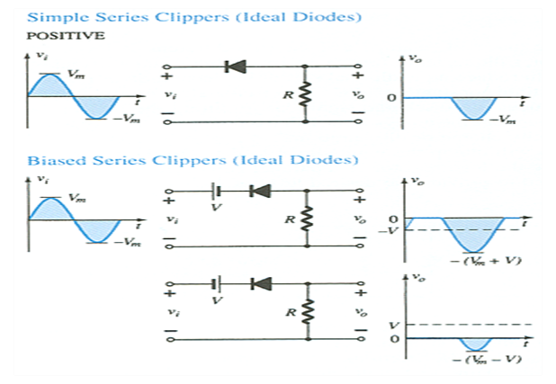
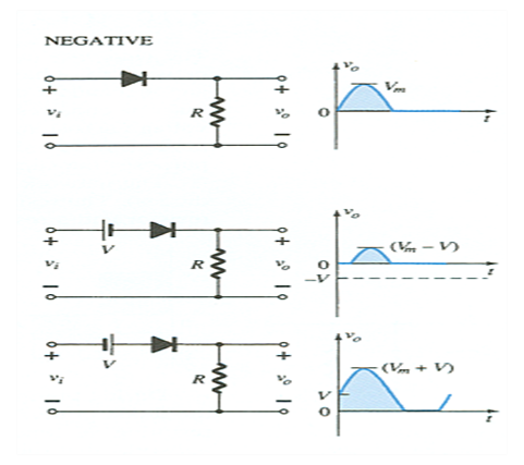
Diode Clipper Circuits:


Diode Clamping circuits:


Voltage Doubler circuit:
- This half-wave voltage doubler’s output can be calculated by: Vout = VC2 = 2Vm, where Vm = peak secondary voltage of the transformer.

Positive Half-Cycle
- D1 conducts
- D2 is switched off
- Capacitor C1 charges to Vm
Negative Half-Cycle
- D1 is switched off
- D2 conducts
- Capacitor C2 charges to Vm
Vout = VC2 = 2Vm

Zener Diode:
- The Zener is a diode operated in reverse bias at the Zener Voltage (Vz).
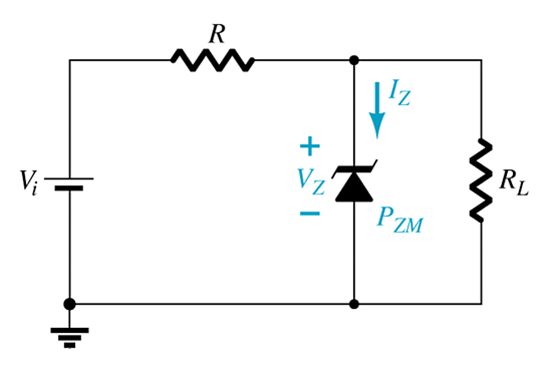
When Vi ³ VZ
–The Zener is on
–Voltage across the Zener is VZ
–Zener current: IZ = IR – IRL
–The Zener Power: PZ = VZIZ
When Vi < VZ
–The Zener is off
–The Zener acts as an open circuit
Objective questions:
1) A 700mW maximum power dissipation diode at 25degree C has 5mW/degree C de-rating factor. if the forward voltage drop remains constant at 0.7 V, the maximum forward current at 65 degrees C is
a) 700mA b) 714mA c) 1A d) 1mA
Ans: b) 714 mA.
Explanation:
P at 25= 700mW;
dP/dT= -5mW/degree C
P at 65 = P at 25- dP/dT * (65-25)= 700-5*40=500mW;
I=P/V=500/0.7=714 mA.
2)For the circuit shown above, using an ideal diode, the values of voltage and current are respectively,
a) -3 V and 0.6 mA b) 3 V and zero c) 3V and 0.6mA c) -3V and zero
Ans: a) -3 V and 0.6 mA
Explanation: I= (3-(-3))/10k= 0.6mA; V=-3 V; diode is in forward bias;
3) A half-wave rectifier has an input voltage of 240V (RMS). if the step-down transformer has a turns ratio of 8:1 . What is the peak load voltage? ignore the diode drop.
a) 27.5 V b) 86.5 V c) 30.0 V d) 42.5 V
Ans: d) 42.5 V
V1rms= 240V, V2rms= 240/8=30 V;
V2peak= 30*sqrt(2)= 42.5 V;
4) Assertion(A): The reverse saturation current approximately doubles for every 10-degree C temperature rise for both Si and Ge materials.
Reason(R): At room temperature, the p-n junction voltage decreases by about 2.5mV/degree C with rising in temperature.
a) Both A and R are individually true and R is the correct explanation of A
b) Both A and R are individually true but R is not the correct explanation of A
c) A is true but R is false
d) A is false but R is true
Ans: b) Both A and R are individually true but R is not the correct explanation of A
Explanation: Refer above topic
5) Assertion(A): Cut-in voltage for the Germanium diode is greater than that for the Silicon diode.
Reason(R): Germanium diode has a higher reverse saturation current than the Silicon diode.
Ans) d) A is false but R is true
Explanation: Refer above topic
6) When a junction diode is used as a half-wave rectifier with purely resistive load and sinusoidal input voltage, what is the value of the diode conduction angle(where Φ is the ignition angle corresponding to the cut-in voltage)?
a)π b)π-Φ c)π-2Φ d)Slightly greater than π
Ans: c)π-2Φ
7) Consider the following statements for a p-n junction diode:
1. it is an active component
2. Depletion layer width decrease with forward biasing
3. In the reverse biasing case, saturation current increases with increasing temperature
which of the statements given above is correct?
a) 1,2 and 3 b) 1 and 2 c) 2 and 3 d) 1 and 3
Ans: a) 1,2 and 3.
8) Which one of the following statements is not correct?
a) Reverse saturation current in a BJT approximately doubles for every 10-degree C rise in temperature.
b) The reverse resistance of a junction diode increases with an increase in temperature
c) Reverse saturation current of a silicon diode is much smaller than that of a germanium diode.
d) The cut-in voltage of silicon diode is larger than that of germanium
Ans: b
Explanation: Refer above topic
9) When a positive DC voltage is applied to the n-side relative to the p-side, a diode is said to be given a
a) forward bias b) reverse bias c) zero bias d) neutral bias
Ans: b) reverse bias
Explanation: Refer above topic
10) A combination of two diodes connected in parallel when compared to a single diode can withstand
a) twice the value of peak inverse voltage
b) twice the value of the maximum forward current
c) a larger leakage current
d) twice the value of the cut in voltage
Ans: b) twice the value of the maximum forward current
11) The AC resistance of a forward-biased p-n junction diode operating at a bias voltage V and carrying current I is
a) zero b) a constant value independent of V and I c) V/I d) ΔV/ΔI
ans: d) ΔV/ΔI
12)
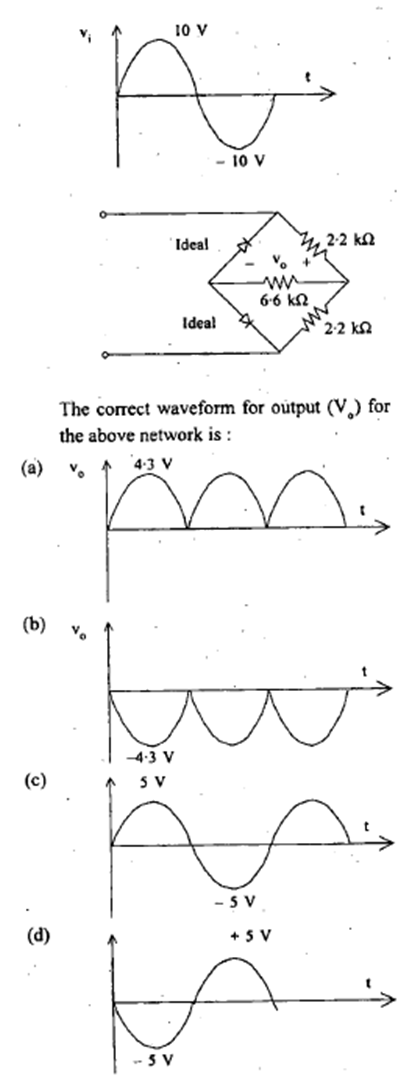
Ans: a
13) A rectifier with a fundamental ripple frequency equal to twice the mains frequency, has a ripple factor of 0.482 and power conversion efficiency equal to 81.2%. The rectifier is
1. bridge rectifier
2. full wave (non-bridge rectifier)
3. half wave rectifier
which of these is correct?
a) 2 and 3 b) 2 only c) 1 and 2 d) 1,2 and 3
Ans: c) 1 and 2
14) Consider the following statements:
When compared with a bridge rectifier, a center-tapped full-wave rectifier
1. has a larger transformer utilization factor
2. can be used for floating output terminals i.e., no input terminal is grounded
3. needs two diodes instead of four
4. needs diodes of lower PIV rating
Which of the above statements is correct?
a) 1 and 2 b) 1,2,3 and 4 c) 3 only d) 3 and 4
Ans: c) 3 only
15)
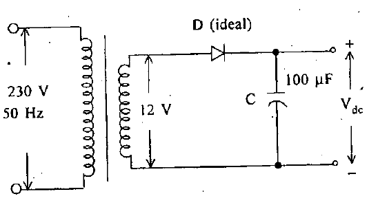
The output Vdc from the above circuit is
a) 12√2 b) 12/π c) 24/π d) 12/√2
Ans:b) 12/π
16)

Ans: c) 2Vm
Explanation: Voltage doubler circuit
17) Silicon diodes are less suited for low-voltage rectifier operation because
a) it cannot withstand high temperatures
b) its reverse saturation current is low
c) its cut-in voltage is high
d) its breakdown voltage is high
Ans: c) its cut-in voltage is high
Explanation: Refer above topic
18)

100 ohm
in the given circuit D1 is an ideal germanium diode and D2 is a silicon diode having a cut-in voltage of 0.7 V, forward resistance of 20 ohms, and reverse saturation current of 10 mA. What are the values of I and V for this circuit respectively?
.
a) 60 mA and zero b) 50 mA and zero c) 53 mA and 0.7V d) 44mA and 1.58V
Ans: a) 60 mA and zero
Explanation: V=0; I=6/100= 60 mA
19) Consider the following statements:
A clamper circuit
1. adds or subtracts a DC voltage to or from a waveform
2. does not change the shape of the waveform
3. amplifies the waveform
Which of the following statements given below is correct?
a) 1 and 2 b) 2 and 3 c) 1 and 3 d) 1,2 and 3
Ans: a) 1 and 2
20) A half wave rectifier having a resistance load of 1kOhm rectifiers an AC voltage of 325V peak value and the diode has a forward resistance of 100 Ohm. What is the RMS value of the current?
a) 295.4 mA b) 94.0 mA c) 147.7 mA d) 208.0 mA
Ans:c) 147.7 mA
Explanation: Rl=1kOhm, Rf=100 Ohm Vm =325 V
Im=Vm/(Rl+Rf)= 325/(1000+100) = 295.45 mA.
Irms=Im/2= 295.45/2=147.7 mA
21) The PIV rating of the diodes used in power supply circuits is chosen by which one of the following criteria?
a) The diodes that are to be used in a fullwave rectifier should be rate 2Vm and in bridge rectifier equal to Vm
b) The diodes that are to be used in a full wave rectifier should be rated Vm and in a bridge rectifier equal to 2Vm
c) All diodes should be rated for Vm only
d) All diodes should be rated for 2Vm
Ans: a) The diodes that are to be used in a full-wave rectifier should be rate 2Vm and in a bridge rectifier equal to Vm
Explanation: Refer above topic
22) Consider the following rectifier circuits
1. Half wave rectifier without filter
2. Full wave rectifier without filter
3. Full wave rectifier with series inductance filter
4. Full wave rectifier with capacitance filter
The sequence of these rectifier circuits in decreasing order of their ripple factor is
a) 1,2,3,4 b) 3,4,1,2 c) 1,4,3,2 d) 3,2,1,4
Ans: a) 1,2,3,4
23) The use of a rectifier filter in a capacitor circuit gives satisfactory performance only when the load
a) current is high b) current is low c) voltage is high d) voltage is low
Ans: b) current is low
Related Topic – click here
- What Is A Diode? Working Principle & Types | Different Types Of Resistors
- What Is Synchronous Speed? | Types & Advantages Of DC Motors
- Working Principle Of Linear Variable Differential Transformer | Construction & Piezoelectric Transducers
- Three-Phase Induction Motor | 3-Phase Induction Motor Principle
- Introduction To Electrical Transformer | Definition, Construction & Parts Of A Transformer | Types Of Transformers
- DC Generator | Principle Of Operation, Construction, Types Of Generators & Application
- What Is DC Motor? | Principle Of DC Motor & Types Of DC Motors
- Diode-Circuits |Diode Convention, Transformer Rectifier & Objective Questions With Answer


