
Digital Electronics
In simple language, the branch of electronics that deals with digital circuits are called digital electronics.
- A continuously varying signal voltage or current is called an analog signal.
For example, a sinusoidal voltage.
- In an analog electronic circuit, the output voltage changes continuously according to the input voltage variations…the output voltage can have an infinite number of values.
- A signal voltage or current which can have only two discrete values is called a digital signal.
For example, a square wave
- An electronic circuit that is designed for two-state operation is called a digital circuit.
These days digital circuits are being used in many electronic products such as video games, microwave ovens, oscilloscopes, etc.
Advantages And Disadvantages Of Digital Electronic
- Advantages of digital electronics
- The disadvantage of digital electronics
Advantages of digital electronics | 5 advantages of digital electronics
1. Digital systems can be normally easily designed.
2. Digital circuits are less affected by noise.
3. Storage of information is easy with a digital circuit.
4. Digital circuits provide greater accuracy and precision.
5. More digital circuitry can be fabricated on integrated chips.
The disadvantage of digital electronics
- The digital circuits can handle only digital signals, it requires encoders and decoders, due to which the cost of the equipment is increased.
2. Under certain situations the use of only analog techniques is simpler and more economical than the process of signal amplification.
3. However since the advantages the disadvantages therefore we are switching to digital techniques at a faster pace.
Digital Circuit
An electronic circuit that handles only a digital signal is called a digital circuit.
or
An electronic circuit in which a state switches between the two-state with time or with the change of the input states, and it is its state at the inputs and the outputs which have significance is called a digital circuit.
Advantages of digital circuit
1. Noise free as output is measured in terms of its state, not in terms of voltage, current, or frequency, a state has a definiteness.
2. Capabilities of logical decision, arithmetic, and Boolean operation on the binary number.
Disadvantage
1. Slower speed due to a greater number of components to represent a state.
2. The circuit has complexities also. To represent a big decimal number a large number of components is needed.
Digital coding

In a digital circuit, each piece of information is defined by an equivalent combination of binary digits. A complete group of these combinations which represent numbers, letters,s or symbols is called digital coding.
The group of Os and 1s in the binary number can be thought of as a code representing the decimal numbers. When a decimal number is represented by its equivalent binary number, it is called straight binary coding.
Types of code
1. BCD code
- It is also known as natural BCD and is very convenient for representing decimal digits in a digital circuit.
- It consists of four bits from 0000 to 1001 representing the decimal numbers from 0 to 9.1010 to 1111 are don’t care about conditions since they do not any meaning in BCD.
2.Excess-3 code
- The code can be derived from BCD by adding 3 to each coded number. It is useful when it is desired to obtain the 9’s complement of a decimal represented by this code. The 9’s complement is obtained simply by complementing each bit.
- This code can be conveniently used for performing subtracting operations on digital computers.
3. Gray code.
- In this code only a bit changes between any two successive numbers.
- It is mainly used in the location of angular positions of a rotating shaft.
4. Octal code
- The octal system is an 8-base system.
- It bases 3 bits to represent one octal digit.
5. Hexadecimal code
- The hexadecimal system is a base 16 system.
- It uses four bits to represent 0 to 9 continued by alphabetical characters from A to F.
Logic Gates
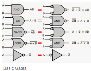
A digital circuit with one or more input signals but only one output signal is called a logic gate. Or
A logic gate is an electronic circuit that makes logical decisions.
Types of logic gate
1. NOT Gate 2.NAND Gate
3. AND Gate 4. OR Gate
5. NOR Gate 6.XOR Gate
Related post
Difference-Between-Microprocessor-And-Microcontroller
8085 Microprocessor-Based Stepper Motor Control System
Interfacing Of 8257 With 8085 Processor
Vector Groups | Application Of Transformer According To Vector Group
Interphase Mass Transfer |Mass Transfer Basics
Oxygen Production Plant Flow Sheet | Nitrogen Production Plant Flowsheet


