
Various process options used for desulphurisation technology:
1. SYN/SAT technology
2. Unisol
3. Hydro Desulphurization (HDS)
Diesel Hydro desulphurization (HDS) Process:
The purpose of the HDS unit is :
1. To perform desulfurization of the reactor feed. The specification to meet is 500ppm wt.
2. The hydrogenation of eventual olefin structures (achieved easily using a special catalyst )
Main chemical reaction mechanisms that influence the process:
1. Refining reactions.
2. Hydrogenation reactions.
(a). Refining reactions
Desulfurisation: Mercaptans, sulfides and disulphides easily react, leading to the corresponding saturated or aromatic compounds. Sulphur combined into cycles of aromatic structure, like thiophene is more difficult to eliminate. These reactions lead to H2S formation and hydrogen consumption.
Denitrification: The denitrification reaction rate is lower than that of desulphurization. it occurs mainly in the case of heterocyclic compounds having an aromatic structure(pyridine for example). These reactions lead to NH3formation and H2 consumption.
(b). Hydrogenation reactions :
- These reactions affect the Diolefins, olefins and aromatics and are highly exothermic. Diolefins and olefins are converted into saturated compounds.
- The hydrogenation rate of aromatics is limited.
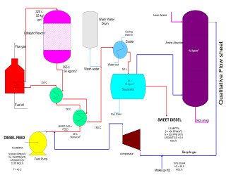
- The feed to the DHDS (Diesel Hydro Desulphurisation section) unit is a blend of straight run and cracked gas oils. The feed blend is filtered through a feed filter package and sent to the feed surge drum. The pressure in the feed surge drum is maintained by fuel gas blanketing.
- The liquid phase feed is pumped under flow control by a feed pump, mixed with the hydrogen recycle compressor delivery stream and let in the heat exchanger train. This mixing of recycled hydrogen with feed ensures an adequate hydrogen partial pressure at the inlet of the reactor train. A polymerization inhibitor is injected.
- The hydrogen make-up gas coming from B/L is routed through chlorine adsorbent and is then compressed by the compressor. The part of the gas is sent as quench gas to the reactor. The mixed stream (feed + recycle hydrogen) is heated in the first feed/effluent heat exchanger then in the second feed/effluent exchanger and finally in the reactor heater to the required reactor inlet temperature.
- The reactor inlet temperature is maintained by controlling the fuel gas/fuel oil to the heater burners. The stream is then let in the reactor which includes a catalyst in three beds.
- Cold quenches of hydrogen coming from the recycling compressor are added at the inlet of each new bed to control the bed inlet temperature.
- The reactor effluent is cooled in the heat exchangers. To avoid ammonium salt deposits and the risk of corrosion, water is injected at the inlet of the effluent cooled. This mixture is collected in the cold separator where three phases are separated.
- The sour water containing ammonium salts is partly recycled for washing.
- The gas phase from the cold separator goes to the amine absorber where H2S is removed. In the amine absorber, the gas is washed by a 25%wt DEA solution. The lean DEA solution is pumped by the DEA booster pump to the top of the absorber. The rich DEA solution is withdrawn from the bottom of the absorber to be fed to the regeneration section. The gas from the absorber contains hydrogen which is recycled back to the reactor.
- The hydrocarbon liquid is withdrawn from the separator and sent to storage which is our product.
Predesulphurization of Naphtha process description:
Hydrogenation and stripping are the primary processes to remove bulk sulphur present in naphtha. Sulphur is a harmful component in raw naphtha when used as primary stock in ammonia production. Sulphur is treated as an impurity which has a huge impact on the production cost of ammonia. It is a poisoning element for steam naphtha reforming catalyst it should be removed from raw naphtha. The process involved in the removal of sulphur impurity is called Pre-desulphurization since another final desulphurization system is been established in present process ammonia manufacturing plants along with PDS because of the availability of raw naphtha containing sulphur of about 1500 ppm which is not desirable to present technology catalyst. This fraction is reduced to 10 to 5 ppm in Pre-desulphurization, and final desulphurization is used to absorb the remaining traces of sulphur.
Unit operation equipment used in this process are:
- Deaerator
- Recycle compressor
- Feed effluent heat exchangers
- Fired heater
- Hydrogenator (fixed packed bed reactor)
- Effluent separator
- Naphtha stripper
The raw naphtha is passed through a deaerator to remove oxygen content dissolved in the liquid naphtha using natural gas or naphtha vapours, this operation will prevent the risk of gum formation in heat exchange equipment. The stripped off-gas from the deaerator is used as fuel and the liquid naphtha from the deaerator is pumped through a series of effluent heat exchangers to vaporize and then to the superheated fired heater. Sulphur present in the form of mercaptan, thioether, and disulphide is made to react with hydrogen and form hydrogen sulphide at Hydrogenator. The reaction is exothermic the heat obtained is used to preheat the inlet feed to the fired heater before the reactor to attain the reaction temperature. Hydrogen gas is added at the compressor section to the liquid stream of deaerated naphtha. The mixture at 40 kg/sq.cm pressure is passed to the effluent heater and vaporized to a temperature of 300degC. This temperature is raised to 380 deg C by the fired heater and passed to the top side of the fixed-packed bed catalytic Hydrogenation reactor. Most of the sulphur is reacted with hydrogen as per the equation.

Where R, is a radical of hydrocarbon.
The reaction mixture is cooled to separate the naphtha and hydrogenated gas. Liquid naphtha which is cooled is fed to a stripper to strip out dissolved water and hydrogen sulphide. The stripper feed preheater is used to preheat the feed naphtha by the naphtha stream obtained from the bottom of the stripper which is at a temperature of about 200-250 deg C. Stripper is a distillation column having around 20 trays and operates at 10kg/sq cm. Temperatures are maintained around 200 to 130 deg C at the bottom and 130 to 90 deg C at the top depending on feedstock. Off gases are used as fuel and the naphtha obtained at the bottom is called sweet naphtha. Sweet naphtha should contain less than 15 ppm of total sulphur.

