
DC Potentiometer
A DC Potentiometer is used for the measurement of EMFs of different cells and for calibrating the voltmeters, ammeters, wattmeters, etc. These potentiometers consist of a germen silver or manganin wire. This wire is one meter long and it is stretched between two terminals. This wire is connected with Rheostat in series. As shown in the figure below:

Measurement of EMF by DC Potentiometer
The switch and the slide wire are set to the standard cell voltage. The standard voltage is 1.01 volts. The switch S is in calibrate position and the galvanometer switch K is pressed when the rheostat is adjusted to zero. A 10Kw resistance is included in a circuit to protect the Galvanometer from overloading. When the null deflection on the galvanometer comes near, then the protective resistance is shorted to increase the sensitivity of the galvanometer. The rheostat is adjusted for the deflection of the galvanometer. Now, the switch is closed to connect the unknown emf with the protective resistance in the circuit. The potentiometer is adjusted by means of a main dial and a slide wire. The balance is obtained and the value of the unknown EMF is measured.

Applications of DC Potentiometer
DC Potentiometer is used for the measurement of various electric parameters and for the calibration of different instruments. The uses of DC potentiometer are described below:
- Measurement of Electric Current
- Measurement of Voltage
- Measurement of Resistance
- Measurement of Electric Power
- Calibration of Ammeter
- Calibration of Voltmeter
- Calibration of Wattmeter
So, let’s discuss all these measurements and calibrations of instruments with the help of a DC Potentiometer one by one:
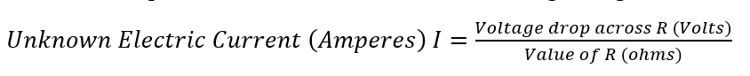
Measurement of Electric Current
In this method, the current which is to be measured by the DC potentiometer is passed through the standard resistance/resistor R as shown in the figure. The standard resistor should be of a value by which voltage drops are caused by the flow of electric current which is to be measured and its value may not be exceeded to the value of the potentiometer. The following formula is used to measure the unknown electric current in amperes from this circuit which is shown in the figure is given below:

Measurement of Voltage
In this method of measurement, the DC potentiometer measures the high voltage. These high voltages are measured by the volt-ratio box with the potentiometer. This box consists of simple resistance with various taps on its input side as shown in the figure. Each input terminal has its own maximum voltage and these are corresponding to the multiplying factor for the voltage scale.
High voltage is applied to the input terminal of the volt-ratio box/voltage divider and these high voltage leads to the potentiometer through the voltage divider and the two points are taken by the potentiometer from the volt-ratio box. The high voltage is measured by the potentiometer. The formula to measure the high voltage is given below:
Where v is the voltage measured by the potentiometer and k is the multiplying factor of the volt-ratio box.

Measurement of Resistance
The resistance which is to be measured is connected in series with the standard resistor. The rheostat is connected in this circuit to control the electric current and an Ammeter is also connected in series with the rheostat and it is used to indicate the value of the current is within the limit of the potentiometer or not. The two-pole double throw switch is connected between the unknown resistance which is to be measured and the standard resistance. When this switch is put into 1 position, the unknown resistance is connected to the potentiometer. The reading of the potentiometer is in VR. then,
And when the switch is thrown to the 2 positions, the standard resistance S is connected to the potentiometer. This reading of the potentiometer is in VS then the value of unknown resistance is measured correctly. The formula is given below for the measurement of resistance:

Measurement of Electric Power
In this method, the standard resistance is connected across the load. The voltage drop is divided across the standard resistor then the load current will be,
Where VS are voltage drops across the standard resistors as measured by the potentiometer. The total power consumed in a circuit is given below in the form of the formula:

Calibration of Voltmeter
In this calibration, a stable DC voltage supply is used and a potential divider network is used which consists of two rheostats. One rheostat is used for coarse and the other is used to control the calibrating voltage. These controls are used to adjust the supply voltage. The volt-ratio box steps down the voltage across the voltmeter. These voltages are suitable for the voltmeter reading. The potentiometer measures the accurate value of voltage and if the reading of the voltmeter and potentiometer does not match with each other then there will be opposite connections of the voltage supply in the circuit.

Calibration of Ammeter
In this method, the standard resistor is connected in series with the ammeter. This resistor carries a high value of current. The voltage drop and the current are measured across the standard resistor with the help of a potentiometer by dividing the voltage across the standard resistor with the standard resistor value. The following formula is used to measure the current from the potentiometer:
Where VS is the voltage across the standard resistance and S is the value of standard resistance.

Calibration of Wattmeter
In this method of calibration, the current coil of the wattmeter is connected to the low-voltage supply, and the voltage coil is connected to the normal supply through the voltage divider. The voltage across the voltage coil is measured by the potentiometer directly. The current of the current coil of the wattmeter is measured by measuring the voltage drop across the standard resistance.
The power will be VI where V is the voltage across the voltage coil and I is the electric current through the current coil of the wattmeter.

Related keyword
- Potentiometer working principle
- Construction of DC potentiometer
- DC potentiometer applications
- Voltage measurement using a potentiometer
- Current measurement using a potentiometer
- Resistance measurement using a potentiometer
- Power measurement using a potentiometer
- Accuracy of DC potentiometer
- Null detection method
- Kelvin double bridge
- Calibration of DC potentiometer
- Voltage ratio measurement
- Load regulation measurement
- Temperature coefficient compensation
- High-precision voltage measurement


