
Definition:
“An electrical generator is a device which converts mechanical energy into electrical energy. DC generator produces direct current”.

PRINCIPLE:
In a DC generator, an emf is induced whenever magnetic flux is cut by a conductor.
WORKING:

Shown in the above figure is a rectangular copper conductor loop ABCD rotating in a clockwise direction about its own axis in a uniform magnetic field provided by permanent magnets or electromagnets.
Two ends of the coil are connected to two slip rings R1 and R2 which are insulated from each other and from the central shaft.
Two collecting brushes B1 and B2 made of carbon or copper are pressed against the slip rings. Their function is to collect the current induced in the coil.
The electric current is produced whenever the coil rotates between the magnetic poles. The deflection of the galvanometer needle shows the current is induced.
Important characteristics of a DC generator:
i. Load saturation characteristic (E0/If): It is also called open-circuit characteristic or No magnetic. It gives the relation between the no-load generated emf in the armature (E0) and the field or exciting current (If). This characteristic is the same for the separately excited and the self-excited generators.
ii. Internal characteristic (Eg/Ia): It practically gives the relation between the emf (Eg) actually induced in the armature conductors (after considering the demagnetizing effect of armature reaction) and armature current Ia. It is also known as total characteristic.
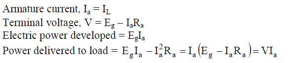
iii. External characteristic (V/Ia ): It shows the relation between the terminal voltage
iv. dc generator is mechanical energy into converted electrical energy which is used in the machine part of the stator in an out part & rioter is the inner part and voltage induced armature winding and current pass is Field winding it is magnetic flux generates.
DC generators are classified based on their method of excitation. So on this basis, there are two types of DC generators:-
1. Separately excited DC generator
2. Self-excited DC generator
Self-excited DC generators can again be classified as 1) DC Series generators 2) DC Shunt generators and 3) DC Compound generators.
Let’s take a brief look at how all these differ.
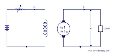
1. Separately excited DC generator
As you can guess from the name itself, this dc generator has a field magnet winding that is excited using a separate voltage source (like a battery). You can see the representation in the below image. The output voltage depends on the speed of rotation of the armature and field current. The higher the speed of rotation and current – the higher the output e.m.f
2. Self-Excited DC Generator
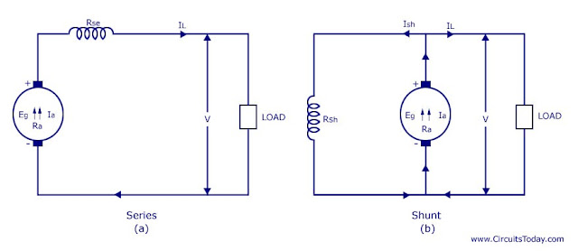
These are generators in which the field winding is excited by the output of the generator itself. As described before – there are three types of self-excited dc generators – they are 1) Series 2) Shunt and 3) Compound.
A series DC generator is shown below in fig (a) – in which the armature winding is connected in series with the field winding so that the field current flows through the load as well as the field winding. The field winding is a low resistance, thick wire of few turns. Series generators are also rarely used!
A shunt DC generator is shown in figure (b), in which the field winding is wired parallel to the armature winding so that the voltage across both is the same. The field winding has high resistance and more number turns so that only a part of the armature current passes through field winding and the rest passes through the load.

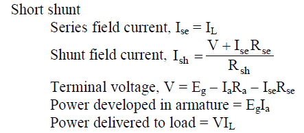
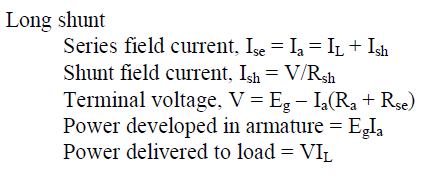
A compound generator is shown in the figure below. It has two field findings namely Rsh and Rse. They are basically shunt winding (Rsh) and series winding (Rse). The compound generator is of two types – 1) Short shunt and 2) Long shunt
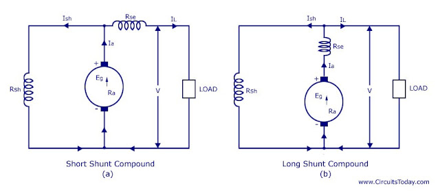
Short shunt:- Here the shunt field winding is wired parallel to the armature and the series field winding is connected in series to the load. It is shown in fig (1)
Long shunt:- Here the shunt field winding is parallel to both the armature and series field winding (Rse is wired in series to the armature). It is shown in figure (2)
So you have got a basic idea about the types of DC generators! Now you may know that these generators are used only for special industrial purposes where there is a huge demand for DC production. Otherwise, electrical energy is produced by AC generators and is transmitted from one place to other as AC itself. When DC power is required, we usually convert AC to DC using rectifiers.
Also read,


