
What is a dc machine?
A DC machine is an electrical machine that converts electrical energy into mechanical energy, or vice versa. DC stands for direct current, which refers to the type of electrical current that flows in one direction. There are two main types of DC machines: DC generators and DC motors.
A DC generator is a device that converts mechanical energy into electrical energy. It typically consists of a rotor (the rotating part) and a stator (the stationary part). The rotor is connected to a prime mover, such as a steam turbine or internal combustion engine, which provides the mechanical energy to turn the rotor. The stator is connected to a field winding, which creates a magnetic field. As the rotor turns, it causes the field winding to cut through the stator’s winding, which induces a current in the stator winding, creating an output voltage.
A DC motor is a device that converts electrical energy into mechanical energy. It also typically consists of a rotor and a stator. The stator is connected to a field winding and the rotor is connected to an armature winding. When an electrical current flows through the field winding, it creates a magnetic field. When an electrical current flows through the armature winding, it interacts with the magnetic field, causing the rotor to turn. The rotation of the rotor provides the mechanical output energy.
DC machines are used in a wide range of applications, including electric vehicles, industrial drives, and electric power generation. They are simple in construction, reliable, easy to control, and have a wide range of speed control. However, DC systems have a lower power-to-weight ratio and are less efficient than their AC counterparts, and are slowly being replaced by AC machines in many applications.
Working OF D.C. MACHINE
The working of a DC machine, whether it is a generator or a motor, is based on the principle of electromagnetic induction. The basic components of a DC machine are the rotor, which is the rotating part, and the stator, which is the stationary part. The stator houses the field winding, which is responsible for creating the magnetic field, and the rotor houses the armature winding, which is responsible for generating or receiving the electrical current.
For a DC generator:
- The rotor is connected to a prime mover, such as a steam turbine or internal combustion engine, which provides the mechanical energy to turn the rotor.
- As the rotor turns, it causes the field winding to cut through the stator’s winding. This induces a current in the stator winding, creating an output voltage.
- The output voltage is a direct current, hence the name DC generator.
For a DC motor:
- When an electrical current flows through the field winding, it creates a magnetic field.
- When an electrical current flows through the armature winding, it interacts with the magnetic field, causing the rotor to turn.
- The rotation of the rotor provides the mechanical output energy.
In both cases, the DC machine converts energy from one form to another. In a generator, mechanical energy is converted into electrical energy and in a motor, electrical energy is converted into mechanical energy.
The speed of the rotor can be varied by controlling the current flowing through the field winding. This is known as field control and is a method of speed control in DC machines. Another method is armature control where the armature current is varied to control the speed.
It’s important to note that DC machines have a limited range of speed and power, and they are less efficient than their AC counterparts, which are slowly replacing DC machines in many applications.
CONSTRUCTION OF D.C. MACHINE
- A dc machine can either be operated as a generator or as a motor.
- Therefore the construction is the same for both the dc generators and the dc motors.
- The sectional view of the dc machine is shown in the following Figure.
The main parts of a dc machine are
1. Yoke or magnetic frame
2. Magnetic poles
3. Field coils
4. Inter poles (or) Commutator poles
5. Armature and Armature coils
6. Commutator and Brushes
7. Bearings and End covers
Yoke or magnetic frame
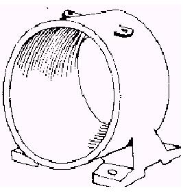
- It is made of cast iron for small machines. Large machines, it is made of cast steel.
Function of yoke
i) It provides mechanical support for the machine and acts as a cover
for the machine
ii) It forms the portion of a magnetic circuit.
Magnetic poles
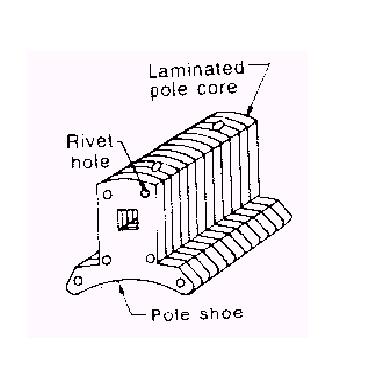
- The field magnet consists of pole cores and pole shoes.
- The pole cores and pole shoes are built with thin laminations of annealed steel and are held together using rivets or under hydraulic pressure.
- These magnetic poles are fitted to the yoke using screws.
- An advantage of pole cores built up of laminations is that eddy current losses in the pole faces are minimized.
The function of pole shoes
(i) They spread out the flux in the air gap and also reduce the reluctance of the magnetic path at its larger cross-section.
(ii) They support the exciting coils or field coils.
Field coils
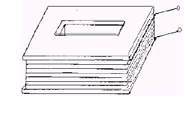
- Field coils are wound with enameled copper wire. Sometimes cotton insulation is used.
- The coils are dried in a vacuum and then impregnated with an insulating compound.
- Sufficient space is left between the layers for ventilating purposes.
- The exciting coils on the inter poles are connected in series with the armature.
- So they carry the full armature current and are made up of a few turns of a heavy conductor.
Interpol or Commutating poles
Inter poles are present in the high capacity dc machines.
The function of Interpol’s or Commutating poles
(i) To improve commutation and
(ii) To reduce armature reaction
Armature and Armature coils
• When the armature is revolving, it is subjected to alternating magnetization.
• This causes hysteresis loss.
• To minimize this loss, low hysteresis steel containing a few percentages of silicon is used in the armature.
• To reduce the eddy current loss, laminations are provided.
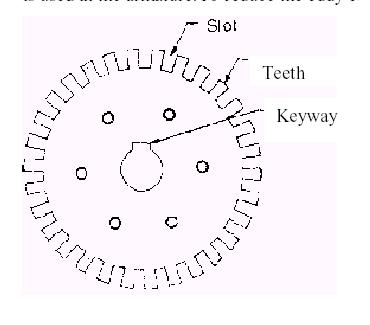
• The armature coils are wound with single cotton-covered or double cotton-covered or enameled insulated wires.
• These coils are put into the insulated slots of the armature to avoid short circuits between the armature conductors and core.
• The slots are closed by fiber or wooden wedges to prevent the conductors from plying out due to the centrifugal force caused by the rotation of the armature.
• The armature is impregnated with varnish and dried. In medium and small machines, circular conductors are used.
• In large machines, rectangular strips of conductors are used for winding the armature coils.
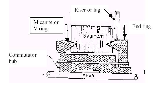
Commutator
• It is made of wedge-shaped segments of hard-drawn (or) drop-forged copper insulated from each other by thin layers of built-up mica.
• The segments are held together by clamping them using Vshaped end rings and insulating from the segments by V-shaped moissanite rings.
• Each segment is provided with a riser to which the leads of the armature coils are soldered.
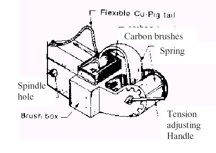
Brushes
• The purpose of the brush is to carry the current from the commutator to the external circuit.
• It is made of carbon or copper. For low-voltage machines, it is made of the copper-carbon compound.
• The brushes are placed in the brush holder, which is kept pressed against the commutator by a spring.
• The brush holder is fitted to a spindle, which is insulated from the machine.
• Connections from the brushes are taken by means of flexible pigtails, made of copper ribbons.
Bearings and End covers
• End covers are made of cast iron or fabricated steel and are fitted to both ends of the yoke.
• To these end covers either ball bearings or roller bearings are fitted and the armature shaft is mounted over these bearings.
• These bearings are lubricated with grease or hard oi
Armature winding fundamentals
• In modern dc machines, drum-type armature windings are provided. In this type, the coils are wound and placed into the insulated slots of the armature.
• A coil with more than one turn is known as a multi-turn coil.
• The coils are always placed in two slots which are approximately one pole pitch apart.
• The portion of a coil placed inside a slot is called the coil side and each coil will have a number of conductors.
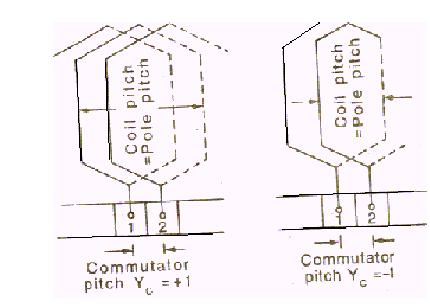
• The distance between the two coil sides of a coil is termed coil pitch, which is expressed in terms of
a number of slots.
• The ends of a coil are connected to two different commutator segments on the commutator.
• The distance in terms of the number of commutator segments, between the commutator segments to which the ends of a coil are connected is called commutator pitch.
• The double-layer windings are present in the dc machine. In double-layer winding, there will be two coil sides belonging to two different coils in each slot.
• If a coil side of one coil is laid in the top layer of a slot, the other coil side of the same coil occupies the bottom layer of the slot usually one pole pitch.
Drum type of winding has two types.
1. Lap winding
2. Wave winding
Lap winding
• In lap winding each coil is connected in series with the next coil under the same pole pair.
• If the start of one coil is connected to one particular commutator segment, the end of that coil and the start of the next coil are connected to the next commutator segment either to the right or left of the first commutator segment.
• This process is continued till all the coils are connected. Here the commutator pitch is always + 1.
• In lap winding there are as many parallel paths as there is a number of poles.
• The emf induced in any generator is equal to the emf induced in all the coils in a parallel path.
• Therefore lap winding is used in low voltage large current dc machines.
Related Topic – click here
- Dynamometer Type Three-Phase Wattmeter
- Three Methods Of Compounding In Steam Turbines
- Classification Of Moving Iron Instruments
- CONSTRUCTION OF D.C. MACHINE
- Three-Point Starter Measuring Instruments
- Electrodynamometer (Electrodynamics) Type Instruments
- STATIC & DYNAMIC CHARACTERISTICS OF ELECTRICAL MEASUREMENT SYSTEM
- Starting Of Induction Motor | Types Of Three-Phase Induction Motor Starting Methods
- Electrical Engineering History Facts Words | History Of E


