
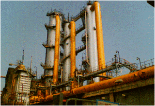
The gas collected at the gas collecting main from the coke oven is cooled by spraying circulating Ammonical liquor. The cooled coke oven gas along with excess liquor enters into the separator. Here the gas and liquor get separated. The coke oven gas from the separator comes to the Primary Gas cooler where the temperature of the gas is reduced from 80 deg C to 30 deg C by means of cooling water.
Primary Gas Cooler:
The coke oven gas from the separator is fed to the PGC from the top. The cooler consists of three zones. This is a shell and tube heat exchanger in which the CO gas exchanges with service water in the top two zones and with chilled water in the bottom zone the tubes are inclined in all the zones. The inclination is maintained at 15°c with the horizontal. This provides any naphthalene condensate to drain easily. The main purpose of PGC is to cool the gas from 90°c to 30°c.
During this cooling process, the naphthalene and traces of tar present in the gas condense and this is collected at the bottom of the PGC. The liquid collected at the bottom is sent to the seal pot by gravity. The level in the seal pot should be maintained constant as this acts as a seal to the gas in the cooler.
Tar at a temperature of 90°c is flushed from the top of the cooler to remove the condensed naphthalene on the tubes. The tar is then collected at the bottom of the seal pot. Tar and naphthalene from the seal pot are fed to the storage tank of the CPH. The CO gas from the bottom of the PGC is fed to the electrostatic precipitator.
• Gas temperature before PGC 80-95°c
• Gas temperature after PGC 27-30°c
• Service water inlet temperature 32-33°c
• Service water outlet temperature 43°c
• Gas condensate flow to each PGC 10-15 Nm3/hr
• Chilled water inlet temperature 11-12°c
Electrostatic Precipitator:
The CO gas enters the ESP from the bottom. Electrostatic precipitators are cylindrical vessels with a conical bottom. Each ESP is provided with a sealed pot. A round disk having electrodes in a suspended state is present inside the precipitator. Electrodes are nothing but SS metal rods. Three are present at the top of the precipitator, which supplies the necessary power to each ESP. A high voltage of about 50,000 volts is supplied to each electrode. Due to high voltage the fine and foggy target slicked to the walls of the electrodes and they fall down due to gravity. The liquid thus collected at the bottom is fed to the seal pot. Each electrode is covered to prevent the connection between any two electrodes.
- Capacity 30,000 Nm3/hr
- Voltage 70KV
- Number of electrodes 148
- ESP insulator boxes temperature 80°C
Final Gas Cooling Plant Process Steps:
- The coke oven gas from the asp plant contains crude benzol and naphthalene and these should be removed from the gas to prevent damage to the pipelines.
- The gas enters the cooler at nearly the middle, it meets the downcoming water, and the naphthalene present in the gas is almost carried away with it to the bottom.
- The gas along with crude benzol is now cooled to 28-30 deg C in a chiller. It then enters
- The scrubber where the benzol in the gas is absorbed into a (solvent) SOLAR OIL
- The solar can be recovered completely by the removal of the crude benzol in it.
- The naphthalene which is carried along with water to the bottom section of the cooler is now treated with TAR so that the naphthalene in the water is absorbed into TAR and both naphthalene and tar can be separated by further treatment
Final Gas Coolers
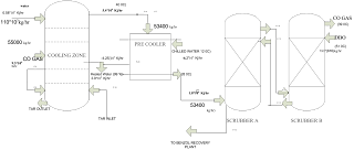
Final Gas Cooling and scrubbing system
From the saturator, the co-gas enter the acid trap where the acid vapors that might be carried along with the co-gas are separated and sent to the saturator. the acid-free vapor of co-gas enters the final gas cooler. There are two final gas coolers with a diameter of 5m & 45.5m in height each cooler has got two sections in the top sections co-gas is sent from the bottom at the top sections and cooled service water is sprayed from the top there is parallel perforated plate aluminum packing of each scrubber which provides the necessary contact time for the water co-gas.
The co-gas enter the final gas coolers min at 55degC cooling of the co-gas is done by direct water spray through a closed cycle system in this way naphthalene that is present in co-gas is scrubbed by water & this enters the bottom of the section. The bottom section naphthalene washer having tar will come in contact with warm water from the top sections lighter than tar the water to the top leaves the cooler. During this process whatever naphthalene is present in the water will get dissolved in tar because of the solubility of naphthalene in tar & many items higher than water this tar is taken out & stored in tanks and sent to the tar distillation plant for processing.
In this scrubber solar oil is used, as a solvent for scrubbing benzol from co-gas benzol is dissolved in solar oil from co-gas. Benzol is dissolved in solar oil from benzolised oil it will be sent to the benzol distillation column where solar oil and benzol are separated the separated solar oil will be recycled again to a scrubber in this way it is a closed system where 1 ton 70-75kgs of oil is consumed because of losses.
Related Topic – click here
- Study Of Hysteresis Of Control Valve | Study Of Inherent Characteristics Of Control Valve
- Selection And Testing Of Bricks And Building Stones For Construction Of Your House | Engineering Construction Marvel Eiffel Tower, Paris
- Concentration Calculation And Methods Of Determining Concentration Of Compounds, Molarity, Molality, And Normality With Solved Example
- Calculation Of Specific Weight, Specific Volume, And Density, Determination Of Gas Constant R
- Computer And Internet Evolution
- Uninterrupted Power Supply, UPS Types, And Details
- Methods For Composition Analysis And Measuring Instruments
- Chemical Oxygen Demand Determination, COD Analysis
- Coke Oven Gas Purification And Cooling Process
