CLASSIFICATION OF POWER SYSTEM STABILITY
A typical modern power system is a high-order multivariable process whose dynamic response is influenced by a wide array of devices with different characteristics and response rates. Stability is a condition of equilibrium between opposing forces. Depending on the network topology, system operating condition, and the form of disturbance, different sets of opposing forces may experience sustained imbalance leading to different forms of instability. A systematic basis for the classification of power system stability is given below.
Need for Classification
Power system stability is essentially a single problem; however, the various forms of instabilities that a power system may undergo cannot be properly understood and effectively dealt with by treating it as such. Because of the high dimensionality and complexity of stability problems, it helps to make simplifying assumptions to analyze specific types of problems using an appropriate degree of detail of system representation and appropriate analytical techniques. Analysis of stability, including identifying key factors that contribute to instability and devising methods of improving stable operation, is greatly facilitated by the classification of stability into appropriate categories. Classification, therefore, is essential for meaningful practical analysis and resolution of power system stability problems.
Categories of Stability
The classification of power system stability proposed here is based on the following considerations:
• The physical nature of the resulting mode of instability as indicated by the main system variable in which instability can be observed.
• The size of the disturbance considered, influences the method of calculation and prediction of stability.
• The devices, processes, and time span that must be taken into consideration in order to assess stability.
The figure gives the overall picture of the power system stability problem, identifying its categories and subcategories. The following are descriptions of the corresponding forms of stability phenomena.
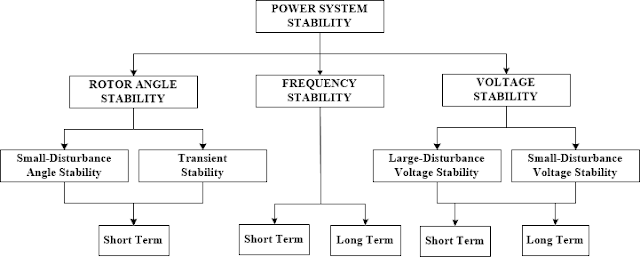 |
| Figure: Classification of power system stability. |
1) ROTOR ANGLE STABILITY:
Rotor angle stability refers to the ability of synchronous machines of an interconnected power system to remain in synchronism after being subjected to a disturbance. It depends on the ability to maintain/restore equilibrium between electromagnetic torque and mechanical torque of each synchronous machine in the system. The instability that may result occurs in the form of increasing angular swings of some generators leading to their loss of synchronism with other generators.
The rotor angle stability problem involves the study of the electromechanical oscillations inherent in power systems. A fundamental factor in this problem is the manner in which the power outputs of synchronous machines vary as their rotor angles change. Under steady-state conditions, there is an equilibrium between the input mechanical torque and the output electromagnetic torque of each generator, and the speed remains constant. If the system is perturbed, this equilibrium is upset, resulting in acceleration or deceleration of the rotors of the machines according to the laws of motion of a rotating body. If one generator temporarily runs faster than another, the angular position of its rotor relative to that of the slower machine will advance. The resulting angular difference transfers part of the load from the slow machine to the fast machine, depending on the power-angle relationship. This tends to reduce the speed difference and hence the angular separation.
The power-angle relationship is highly nonlinear. Beyond a certain limit, an increase in angular separation is accompanied by a decrease in power transfer such that the angular separation is increased further. Instability results if the system cannot absorb the kinetic energy corresponding to these rotor speed differences. For any given situation, the stability of the system depends on whether or not the deviations in angular positions of the rotors result in sufficient restoring torques. Loss of synchronism can occur between one machine and the rest of the system, or between groups of machines, with synchronism maintained within each group after separating from each other.
The change in electromagnetic torque of a synchronous machine following a perturbation can be resolved into two components:
• Synchronizing torque component, in phase with rotor angle deviation.
• Damping torque component, in phase with the speed deviation.
System stability depends on the existence of both components of torque for each of the synchronous machines. Lack of sufficient synchronizing torque results in aperiodic or non-oscillatory instability, whereas lack of damping torque results in oscillatory instability.
For convenience in analysis and for gaining useful insight into the nature of stability problems, it is useful to characterize rotor angle stability in terms of the following two subcategories:
Small-disturbance (or small-signal) rotor angle stability: is concerned with the ability of the power system to maintain synchronism under small disturbances. The disturbances are considered to be sufficiently small that linearization of system equations is permissible for purposes of analysis.
Small-disturbance stability depends on the initial operating state of the system. The instability that may result can be of two forms:
I) Increase in rotor angle through a non-oscillatory or aperiodic mode due to lack of synchronizing torque, or
II) Rotor oscillations of increasing amplitude due to lack of sufficient damping torque.
In today’s power systems, small-disturbance rotor angle stability problem is usually associated with insufficient damping of oscillations. The aperiodic instability problem has been largely eliminated by use of continuously acting generator voltage regulators; however, this problem can still occur when generators operate with constant excitation when subjected to the actions of excitation limiters (field current limiters). Small-disturbance rotor angle stability problems may be either local or global in nature.
LOCAL PLANT MODE OSCILLATIONS:
Local problems involve a small part of the power system and are usually associated with rotor angle oscillations of a single power plant against the rest of the power system. Such oscillations are called local plant mode oscillations.
The stability (damping) of these oscillations depends on the strength of the transmission system as seen by the power plant, generator excitation control systems, and plant output.
INTER-AREA MODE OSCILLATIONS:
Global problems are caused by interactions among large groups of generators and have widespread effects. They involve oscillations of a group of generators in one area swinging against a group of generators in another area. Such oscillations are called inter-area mode oscillations. Their characteristics are very complex and significantly different from those of local plant mode oscillations. Load characteristics, in particular, have a major effect on the stability of inter-area modes.
The time frame of interest in small-disturbance stability studies is on the order of 10 to 20 seconds following a disturbance.
Large-disturbance rotor angle stability or transient stability: as it is commonly referred to, is concerned with the ability of the power system to maintain synchronism when subjected to a severe disturbance, such as a short circuit on a transmission line. The resulting system response involves large excursions of generator rotor angles and is influenced by the nonlinear power-angle relationship.
Transient stability depends on both the initial operating state of the system and the severity of the disturbance.
Instability is usually in the form of aperiodic angular separation due to insufficient synchronizing torque, manifesting as first-swing instability. However, in large power systems, transient instability may not always occur as first swing instability associated with a single mode; it could be a result of the superposition of a slow inter-area swing mode and a local-plant swing mode causing a large excursion of rotor angle beyond the first swing. It could also be a result of nonlinear effects affecting a single mode causing instability beyond the first swing.
The time frame of interest in transient stability studies is usually 3 to 5 seconds following the disturbance. It may extend to 10–20 seconds for very large systems with dominant inter-area swings.
As identified in Figure, small-disturbance rotor angle stability as well as transient stability are categorized as short-term phenomena.
2) VOLTAGE STABILITY:
Voltage stability refers to the ability of a power system to maintain steady voltages at all buses in the system after being subjected to a disturbance from a given initial operating condition.
It depends on the ability to maintain/restore equilibrium between load demand and load supply from the power system. The instability that may result occurs in the form of a progressive fall or rise of voltages of some buses. A possible outcome of voltage instability is loss of load in an area or tripping of transmission lines and other elements by their protective systems leading to cascading outages. Loss of synchronism of some generators may result from these outages or from operating conditions that violate the field current limit.
Progressive drop in bus voltages can also be associated with rotor angle instability. For example, the loss of synchronism of machines as rotor angles between two groups of machines approach 180 causes a rapid drop in voltages at intermediate points in the network close to the electrical center. Normally, protective systems operate to separate the two groups of machines and the voltages recover to levels depending on the post-separation conditions. If, however, the system is not so separated, the voltages near the electrical center rapidly oscillate between high and low values as a result of repeated “pole slips” between the two groups of machines. In contrast, the type of sustained fall of voltage that is related to voltage instability involves loads and may occur where rotor angle stability is not an issue.
The term voltage collapse is also often used. It is the process by which the sequence of events accompanying voltage instability leads to a blackout or abnormally low voltages in a significant part of the power system. Stable (steady) operation at low-voltage may continue after transformer tap changers reach their boost limit, with intentional and/or unintentional tripping of some load. The remaining load tends to be voltage sensitive, and the connected demand at normal voltage is not met.
The driving force for voltage instability is usually the loads; in response to a disturbance, power consumed by the loads tends to be restored by the action of motor slip adjustment, distribution voltage regulators, tap-changing transformers, and thermostats.
Restored loads increase the stress on the high-voltage network by increasing the reactive power consumption and causing further voltage reduction. A run-down situation causing voltage instability occurs when load dynamics attempt to restore power consumption beyond the capability of the transmission network and the connected generation.
A major factor contributing to voltage instability is the voltage drop that occurs when active and reactive power flows through inductive reactances of the transmission network; this limits the capability of the transmission network for power transfer and voltage support. The power transfer and voltage support are further limited when some of the generators hit their field or armature current time-overload capability limits.
Voltage stability is threatened when a disturbance increases the reactive power demand beyond the sustainable capacity of the available reactive power resources.
While the most common form of voltage instability is the progressive drop of bus voltages, the risk of overvoltage instability also exists and has been experienced at least on one system. It is caused by a capacitive behavior of the network (EHV transmission lines operating below surge impedance loading) as well as by under-excitation limiters preventing generators and/or synchronous compensators from absorbing the excess reactive power. In this case, the instability is associated with the inability of the combined generation and transmission system to operate below some load level. In their attempt to restore this loaded power, transformer tap changers cause long-term voltage instability.
Voltage stability problems may also be experienced at the terminals of HVDC links used for either long-distance or back-to-back applications. They are usually associated with HVDC links connected to weak ac systems and may occur at rectifier or inverter stations, and are associated with the unfavorable reactive power “load” characteristics of the converters. The HVDC link control strategies have a very significant influence on such problems since the active and reactive power at the ac/dc junction is determined by the controls. If the resulting loading on the ac transmission stresses it beyond its capability, voltage instability occurs. Such a phenomenon is relatively fast with the time frame of interest being in the order of one second or less. Voltage instability may also be associated with converter transformer tap-changer controls, which is a considerably slower phenomenon.
Recent developments in HVDC technology (voltage source converters and capacitor commutated converters) have significantly increased the limits for stable operation of HVDC links in weak systems as compared with the limits for line commutated converters.
One form of voltage stability problem that results in uncontrolled over-voltages is the self-excitation of synchronous machines.
This can arise if the capacitive load of a synchronous machine is too large. Examples of excessive capacitive loads that can initiate self-excitation are open-ended high-voltage lines and shunt capacitors and filter banks from HVDC stations.
The over-voltages that result when generator load changes to capacitive are characterized by an instantaneous rise at the instant of change followed by a more gradual rise. This latter rise depends on the relation between the capacitive load component and machine reactances together with the excitation system of the synchronous machine. The negative field current capability of the exciter is a feature that has a positive influence on the limits for self-excitation.
As in the case of rotor angle stability, it is useful to classify voltage stability into the following subcategories:
Large-disturbance voltage stability: refers to the system’s ability to maintain steady voltages following large disturbances such as system faults, loss of generation, or circuit contingencies. This ability is determined by the system and load characteristics, and the interactions of both continuous and discrete controls and protections. Determination of large-disturbance voltage stability requires the examination of the nonlinear response of the power system over a period of time sufficient to capture the performance and interactions of such devices as motors, under-load transformer tap changers, and generator field-current limiters. The study period of interest may extend from a few seconds to tens of minutes.
Small-disturbance voltage stability: refers to the system’s ability to maintain steady voltages when subjected to small perturbations such as incremental changes in system load.
This form of stability is influenced by the characteristics of loads, continuous controls, and discrete controls at a given instant of time. This concept is useful in determining, at any instant, how the system voltages will respond to small system changes. With appropriate assumptions, system equations can be linearized for analysis thereby allowing the computation of valuable sensitivity information useful in identifying factors influencing stability. This linearization, however, cannot account for nonlinear effects such as tap changer controls (dead bands, discrete tap steps, and time delays). Therefore, a combination of linear and nonlinear analyzes is used in a complementary manner.
As noted above, the time frame of interest for voltage stability problems may vary from a few seconds to tens of minutes. Therefore, voltage stability may be either a short-term or a long-term phenomenon as identified in Figure 1.
Short-term voltage stability involves the dynamics of fast-acting load components such as induction motors, electronically controlled loads, and HVDC converters.
The study period of interest is in the order of several seconds, and analysis requires the solution of appropriate system differential equations; this is similar to the analysis of rotor angle stability. Dynamic modeling of loads is often essential. In contrast to angle stability, short circuits near loads are important. It is recommended that the term transient voltage stability not be used.
Long-term voltage stability involves slower-acting equipment such as tap-changing transformers, thermostatically controlled loads, and generator current limiters. The study period of interest may extend to several or many minutes, and long-term simulations are required for the analysis of system dynamic performance. Stability is usually determined by the resulting outage of equipment, rather than the severity of the initial disturbance.
Instability is due to the loss of long-term equilibrium (e.g., when loads try to restore their power beyond the capability of the transmission network and connected generation), the post-disturbance steady-state operating point being small-disturbance unstable, or a lack of attraction toward the stable post-disturbance equilibrium (e.g., when remedial action is applied too late). The disturbance could also be a sustained load buildup (e.g., morning load increase). In many cases, static analysis can be used to estimate stability margins, identify factors influencing stability, and screen a wide range of system conditions and a large number of scenarios. Where the timing of control actions is important, this should be complemented by quasi-steady-state time-domain simulations.
The distinction between Voltage and Rotor Angle Stability:
It is important to recognize that the distinction between rotor angle stability and voltage stability is not based on weak coupling between variations in active power/angle and reactive power/voltage magnitude. In fact, the coupling is strong for stressed conditions and both rotor angle stability and voltage stability are affected by pre-disturbance active power as well as reactive power flows. Instead, the distinction is based on the specific set of opposing forces that experience sustained imbalance and the principal system variable in which the consequent instability is apparent.
FREQUENCY STABILITY:
Frequency stability refers to the ability of a power system to maintain steady frequency following a severe system upset resulting in a significant imbalance between generation and load.
It depends on the ability to maintain/restore equilibrium between system generation and load, with minimum unintentional loss of load. The instability that may result occurs in the form of sustained frequency swings leading to the tripping of generating units and/or loads.
Severe system upsets generally result in large excursions of frequency, power flows, voltage, and other system variables, thereby invoking the actions of processes, controls, and protections that are not modeled in conventional transient stability or voltage stability studies. These processes may be very slow, such as boiler dynamics, or only triggered for extreme system conditions, such as volts/Hertz protection tripping generators.
In large interconnected power systems, this type of situation is most commonly associated with conditions following the splitting of systems into islands. Stability in this case is a question of whether or not each island will reach a state of operating equilibrium with minimal unintentional loss of load. It is determined by the overall response of the island as evidenced by its mean frequency, rather than the relative motion of machines. Generally, frequency stability problems are associated with inadequacies in equipment responses, poor coordination of control and protection equipment, or insufficient generation reserve. Examples of such problems are reported in the references. In isolated island systems, frequency stability could be of concern for any disturbance causing a relatively significant loss of load or generation.
During frequency excursions, the characteristic times of the processes and devices that are activated will range from a fraction of seconds, corresponding to the response of devices such as under-frequency load shedding and generator controls and protections, to several minutes, corresponding to the response of devices such as prime mover energy supply systems and load voltage regulators. Therefore, as identified in Figure, frequency stability may be a short-term phenomenon or a long-term phenomenon.
An example of short-term frequency instability is the formation of an under-generated island with insufficient under-frequency load shedding such that frequency decays rapidly causing a blackout of the island within a few seconds. On the other hand, more complex situations in which frequency instability is caused by steam turbine over-speed controls or boiler/reactor protection and controls are longer-term phenomena with the time frame of interest ranging from tens of seconds to several minutes.
During frequency excursions, voltage magnitudes may change significantly, especially for islanding conditions with under-frequency load shedding that unloads the system. Voltage magnitude changes, which may be higher in percentage than frequency changes, affect the load-generation imbalance.
High voltage may cause undesirable generator tripping by poorly designed or coordinated loss of excitation relays or volts/Hertz relays. In an overloaded system, the low voltage may cause undesirable operation of impedance relays.
Related Topic – click here
- What Is A Diode? Working Principle & Types | Different Types Of Resistors
- What Is Synchronous Speed? | Types & Advantages Of DC Motors
- Working Principle Of Linear Variable Differential Transformer | Construction & Piezoelectric Transducers
- Three-Phase Induction Motor | 3-Phase Induction Motor Principle
- Introduction To Electrical Transformer | Definition, Construction & Parts Of A Transformer | Types Of Transformers
- DC Generator | Principle Of Operation, Construction, Types Of Generators & Application
- What Is DC Motor? | Principle Of DC Motor & Types Of DC Motors
- Diode-Circuits |Diode Convention, Transformer Rectifier & Objective Questions With Answer


