
Block diagram of ammonia production and Process description, comparison of different ammonia production methods
Naphtha obtained from the distillation of petroleum crude is used as the source of hydrogen which acts as the reactant for the production of ammonia. One mole of Ammonia requires one mole of nitrogen and three moles of hydrogen as per the stoichiometry equation. Natural gas is the better option for hydrogen sources and has advantages over the naphtha process as most of the unit operations are reduced getting down the installation and production costs.

Many variations of Haber’s process are now being used for the manufacture of synthetic ammonia some varying to such an extent that they are identified by a name often that of the group of men developing them. Important among these are the modified Haber Bosch, Haldor Topsoe, Claude, Casale, Fauser, and Mount Cenis processes.
All of them are fundamentally the same in that nitrogen is fixed with hydrogen as ammonia in the presence of a catalyst but have variations in the construction of equipment their arrangement, the composition of the catalyst, and temperature and pressure used but an ideal process flow sheet becomes the platform for improvement in the process. A simple block diagram shows Haber’s process
Process description: The ammonia synthesis process is shown by the simple block diagram in a series of steps as follows
1. Naphtha gas supply: Naphtha is used as feedstock and fuel for the Ammonia plant and is supplied at the offsite Gas Metering station at a pressure of 44kg/cm2g. After metering offsite, the naphtha gas for process feed is directly received at the Ammonia plant battery limit at 40kg/cm2g and 40oC. Fuel gas is used for burners of feedstock preheater, primary Reformer, Auxiliary superheater and start-up heater in Ammonia plant-Feed gas goes to the Desulphurization unit for sulfur removal, if any, and is subsequently processed to produce synthesis gas for Ammonia production.
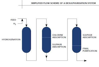
2. Desulphurization: Raw naphtha contains high sulfur which harms the catalyst in the reforming reactor and even consumes hydrogen by undesired side reactions. A packed bed reactor is utilized for the removal of sulfur. A zinc oxide-based bed absorbs the sulfur.
3. Primary reformer: Naphtha contains carbon and hydrogen compounds to separate hydrogen all the carbon is converted to carbon dioxide and hydrogen by means of steam at high temperatures with the presence of the nickel-based catalyst.
4. Secondary reformer: Nitrogen required for the synthesis reaction is obtained from the air so, the carbon dioxide and hydrogen stream is mixed with the air.
5. Shift conversion: carbon mono oxide which is formed in the previous process is converted to carbon dioxide by using steam which results in a shift reaction producing hydrogen. High and low-shift reactors are arranged for this conversion process.
6. CO2 removal: All the carbon dioxide produced is removed by the absorption process. Absorption and stripping towers recover most of the gas which is used in urea production.
7. Methanation: The traces of carbon dioxide and carbon monoxide are converted to methane by means of hydrogen on the catalyst like nickel in the methanation reactor. Heat is produced due to the exothermic reaction.
8. Ammonia synthesis reactor: Iron acts as the catalyst at a temperature of 400oC and pressure of 142kg/cm2g the reaction proceeds for the formation of ammonia.
9. Chilling system: A compression absorption refrigeration system is used for the liquefaction of ammonia. At 1 atm the boiling point of ammonia is -33oC.

A Table of Process Design Modifications in Ammonia Production:
Ever-evolving technologies are been adopted by modern industries to improve the conversion rate with efficiency and less energy consumption for the complete process, some of the competitive designed techniques are given and much more are to be introduced.
| Process | Pressure, atm | Temperature, 0C | Conversion,% |
| Mont Cenis | 120 | 400 | 8-20 |
| Stamp Carbon | 310 | 500 | 10-30 |
| Faster-Montecatini | 220-230 | 500 | 10-30 |
| Casale | 500-700 | 500 | 15-25 |
| Clued | 330-630 | 540-590 | 15-25 |
| Haber Bosch | 330 | 500-550 | 10-30 |
| Nitrogen Eng.Corp | 200-300 | 500-550 | 10-30 |
| Lummus | 270-330 | 500-510 | 10-25 |
| Kellogg | 300-350 | — | 10-30 |
| Du Pont | 900-1000 | 500-600 | 40-80 |
Related topic click here
- Block Diagram Of Ammonia Production And Process Description, Comparison Of Different Ammonia Production Methods
- Ammonium Sulphate Production From Coke Oven Gas Containing Ammonia When Reacted With Sulphuric Acid
- NITRIC ACID Production Process
- Interphase Mass Transfer |Mass Transfer Basics
- Microprocessor 8085 Functional Blocks


