• Varying the armature voltage varies the speed of the dc motor and e field voltage is kept
constant. A controlled rectifier using SCR develops the required armature voltage and the uncontrolled rectifier generates the required field voltage.
• The microprocessor controls the speed of the motor by varying the firing angle of SCRs in the controlled rectifier.
• The system has EPROM for system program storage, and RAM for temporary data storage and stack.
• A keyboard has been provided to input the desired speed and other commands to operate the system.
• In order to display the speed of the motor, a 7-segment LED display has been provided. The keyboard and 7-segment LED display have been interfaced to 8085 based system using the Keyboard display controller INTEL 8279.
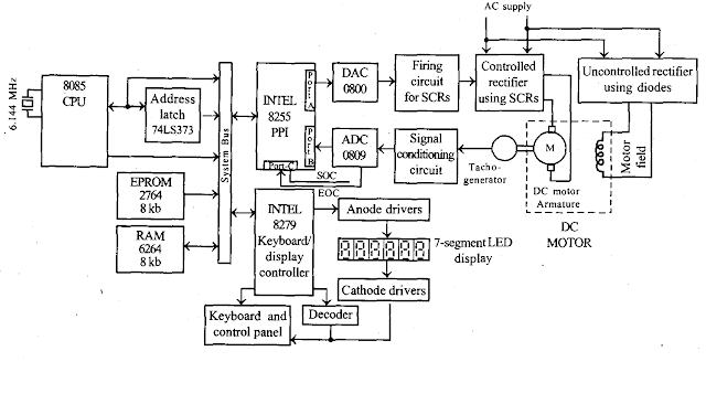
• The speed of the dc motor is measured using a tacho generator. It produces an analog voltage proportional to the speed of the motor.
• Then the analog signal is scaled to the desired level by the signal conditioning circuit and digitized using ADC. (The processor cannot process the analog signal directly, hence the analog signal is digitized using ADC).
• The ADC is interlaced to the 8085 processor through port-B and port-C of 8255. The processor can send a start of conversion to ADC through a port-C pin and at the end of conversion, it can read the digital data from port-B of 8255. This digital data is proportional to actual speed.
• The processor calculates the actual speed and displays it on LEDs.
• Also, the processor compares the actual speed with desired speed entered by the operator through the keyboard. If there is a difference then the error is estimated. The error can be modified by a digital control algorithm, (P/PI/PID/FUZZY logic control algorithm) to produce a digital control signal.
• The digital control signal is converted to an analog signal by the DAC. The analog signal is used
to alter the firing angle of SCRS in the controlled rectifiers. The operational speed control system is shown in the following flowchart.


